 Ax Staining, Axles, Alternator, Fuel Lines, and more
This week started slow, but lots of projects piled up! Starting off with trying to get my ax to stain darker, getting shock brackets and a torque reaction spring to restore, removing bearings and racers from the rear axle, new axle drums, and what started as making the fan belt tighter that turned into a huge multi-day project!
Looking up and over the Jeep. it was a packed week! Mostly some good news on things, but also some bad news. So let’s get going!
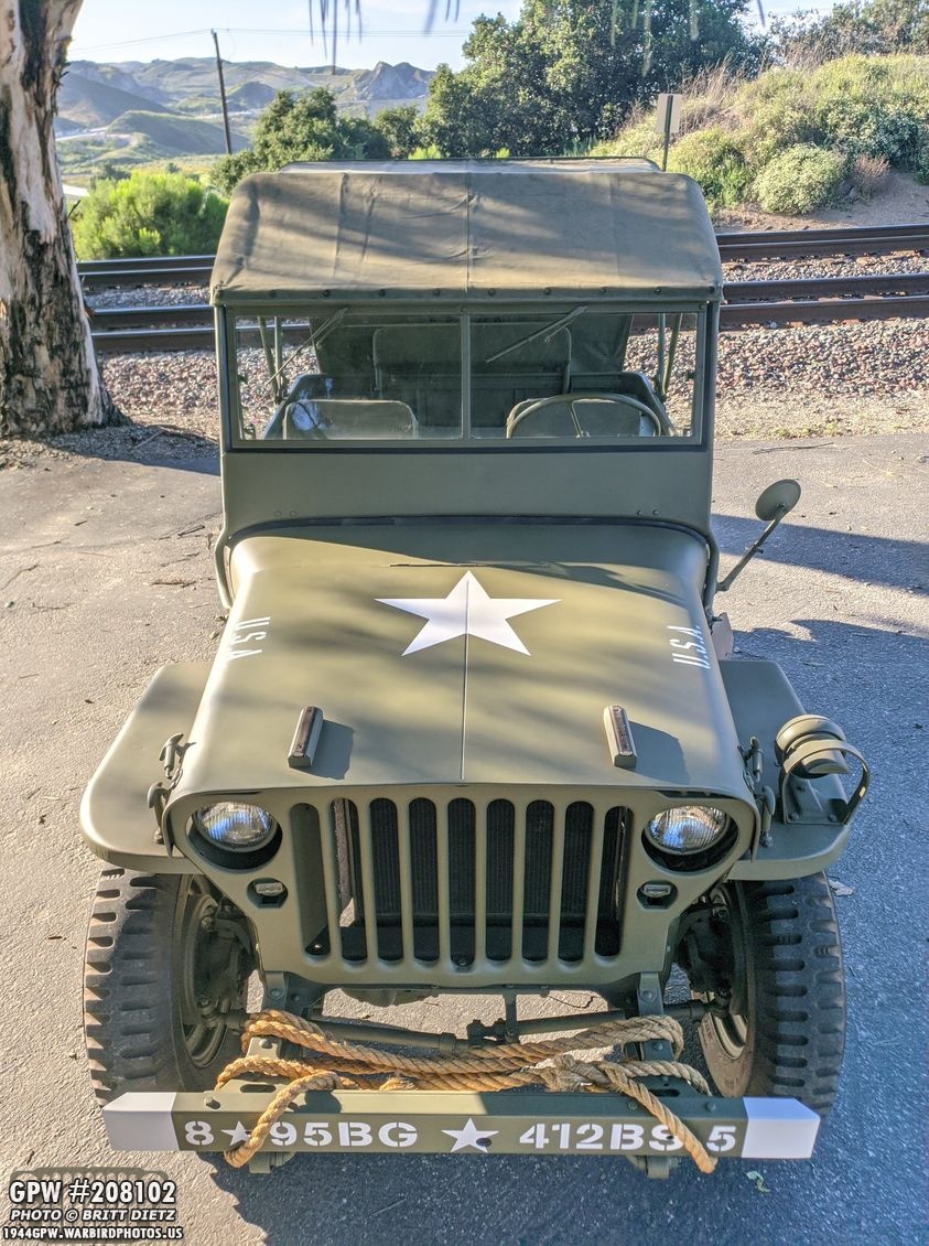
Last week’s update I ended with talking about how I never liked the brightness of the wooden handle. Even after sanding it down to the wood and staining it multiple times, it just wouldn’t take the stains. So, I re-sanded it last week and started over. I stained it two times with a new stain (bottom photos) and it made it darker, but still not by much.

So, with it still not taking the stains, I decided to go super dark with a stain and see if maybe it would get it dark. As you can see here, I put DARK stain on and coated it well. Even though it looks like I went too dark, once I took off the excess it STILL went lighter. But, it was darker, so after drying I did it one more time. Having stained it now 5 times, I decided that was as good as it’s going to get as this wood has something weird about it. So I sprayed it with a matte overcoat and the result was…

It’s better! A LOT better in fact, but it’s still not as dark as the shovel wood. Considering that’s after 5 stainings, it’ll have to do. I could spray paint, but that wouldn’t look as natural. I’ll take better photos of both of them hopefully next week.

I got a bunch of items I needed for the Jeep from a fellow GPW owner here on Facebook. He was selling these items, along with others, that were taken off another Jeep. At the top, I got two shock brackets for my rear shocks (next image will explain more). The rest of the items are a full set for a torque reaction spring. My Jeep, since it has CJ axles and a CJ steering system was missing this crucial item that helps stop a left hand pull of the Jeep when braking. I’ll explain what this all is and why it’s needed in a future update when I install it. All items will need extensive cleaning and restoration, but are all in good order.

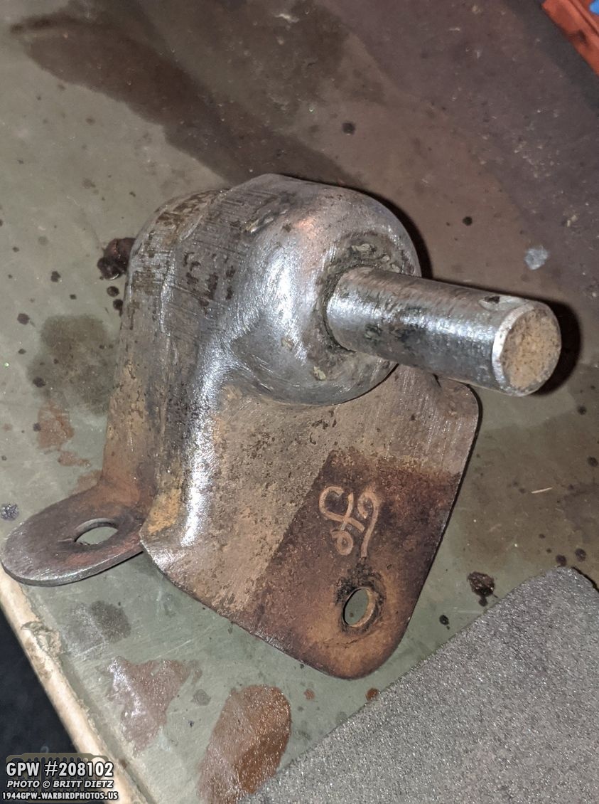
I noticed a few months ago that the rear shocks on my Jeep were connected in an odd spot. There should be a bracket in that groove area that holds the shock, shown bolted below where it should be in one of the holes that usually have the rivet that holds the bracket on. It’s possible this bracket was damaged some time ago, and instead of replacing it, whoever restored the Jeep just put the shock below it. My front shocks have the correct brackets.

Here’s the two rear shock brackets I got. As you can see, they were pretty rusty. Most might have given up on them as they seem to have seen better days. But they looked pretty structurally sound and just need some work! The rivets holding these onto the frame were cut off, so I’ll figure out a way to put them on my frame.
Here’s a look at the two F stamps on these two shock brackets. Time to get to work on restoring them!

To see how well they’d clean up, I took a sanding block and just did a quick sanding, and already it’s starting to look better!
I dipped both of them in EVAPORUST solution for 12 hours. I didn’t have enough of the solution to completely submerge them, so every 12 hours I had to shift the bracket a different way. As you can see, there’s only the area of the F stamp that wasn’t in the solution and it already looks amazing. After soaking that final area in the solution, I then washed/dried it out and took it to the sandblaster…
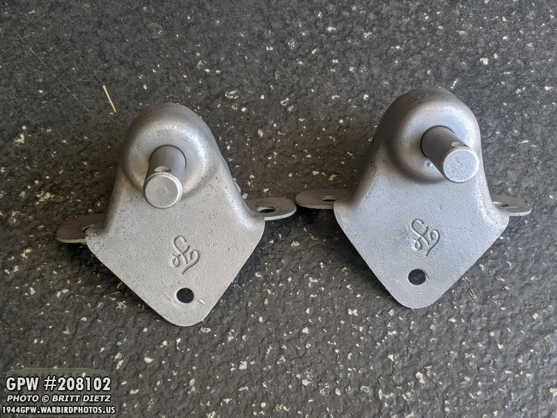
And BOOM. Totally look brand new. What a difference! Switch to the next image to see the before and after together…
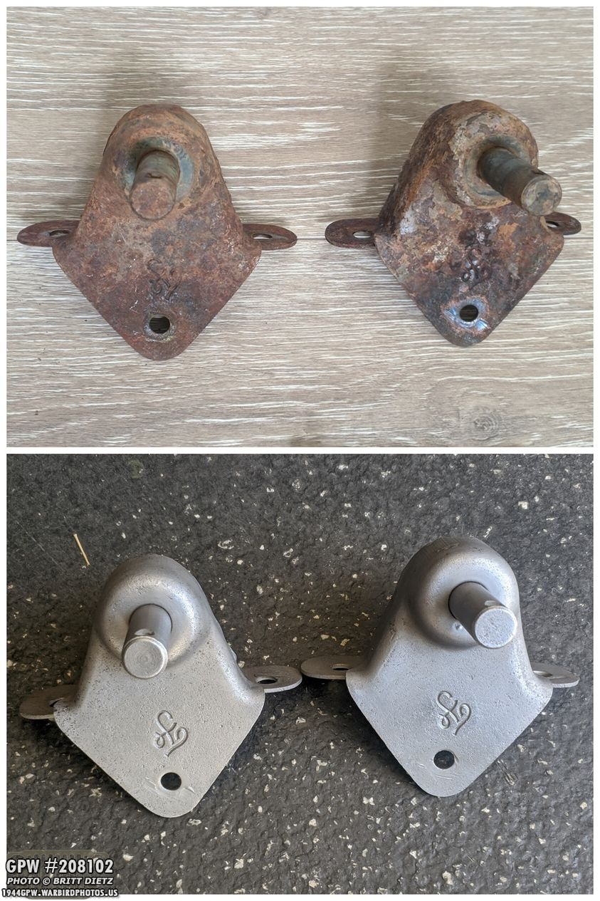
Before and after. Just goes to show that many things, even looking like they are beyond repair, can still be holding a surprise under the rust! I’m SUPER happy how they turned out.

There is still some pitting on them, but they are totally usable and, once painted, will look even better as much of that pitting will be filled.

Before painting, I sprayed the inside with a rust reformer spray paint to help stop any rust that I couldn’t get to and prevent any future rust that would have formed in there from any moisture.

First coat of &Ron Fitzpatrick Jeep Parts Red Oxide Barrier III paint!

And after the second coat. I masked the main bar to keep off the paint. Next week I’ll hit it with OD Green!

Turning to the torque reaction spring hardware, I put them in the EVAPORUST and then sandblasted them. These items came out looking new!

Especially this bracket, it came out better than I expected given all the paint on it.

The two shackles, however, have seen better days. They are pitted pretty good. They might be useable, but I’m not sure on the bushings. I might have to replace those. The left shackle has what looks like a WO on it, but that’s all I can make out. It appears there was something next to the O.

Last week I got an original GPW drag link for when I replace the CJ axles with the GPW ones. I’ve cleaned all the paint and rust off the drag link and it now looks brand new. I masked off the openings…
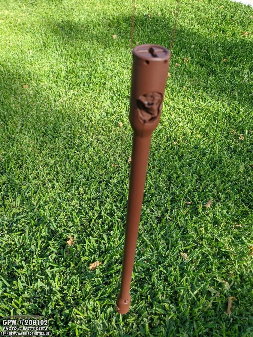
And hit it with the Red Oxide primer. Sorry for the out of focus photo. Next up next week, OD Green!
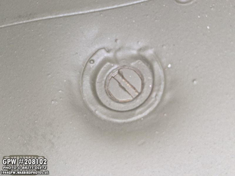
A few weeks ago I posted how I made my own custom drain plug bolts having got 1/4NPT slotted plus and realizing the tub had a weird 7/16 thread. I took those 1/4npt plugs and manually turned them into 7/16 with a belt sander, a flap wheel, and a tap/die set. I wasn’t happy, though, with how they came out. It bothered me a lot.

When I was at Home Depot, I noticed they had 7/16 bolts, and that gave me an idea. I bought a 2 inch 7/16 bolt with the idea of cutting it up into two plugs.

I was able to take a cut off disk and but two perfectly lengthed plugs. I then used the belt sander to smooth it out, and then used the cut off disc to make a slot. On the left shows the second plug I made (took almost all of the bolt to make both plugs). On the right shows the new and old… the gold plug was my attempt I wasn’t happy with. It was messy, the threads were not deep, and the slot was messed up. The new ones are perfect.

And here’s one of the new ones in the drain hole. Looks PERFECT! I painted them OD Green, but forgot to take some photos of them all painted up, so next week I’ll be sure to post them. I’m happy with how these turned out!
Moving on to the axles, in the usual summary… I have CJ axles on my Jeep (came with the Jeep when I bought it) along with a CJ system. I’ve been restoring two wartime (1943) GPW axles to eventually replace the CJ axles. It’s been a long slow process.
I hadn’t driven out the rear axle’s pinion bearings/racers and the oil seal. Was able to get them out after a bit of work. Here’s the yoke side items.
I have new oil seals, but here’s a look at the marking I found on the original oil seal.

And the pinion drive slinger had a nice F stamp on it.
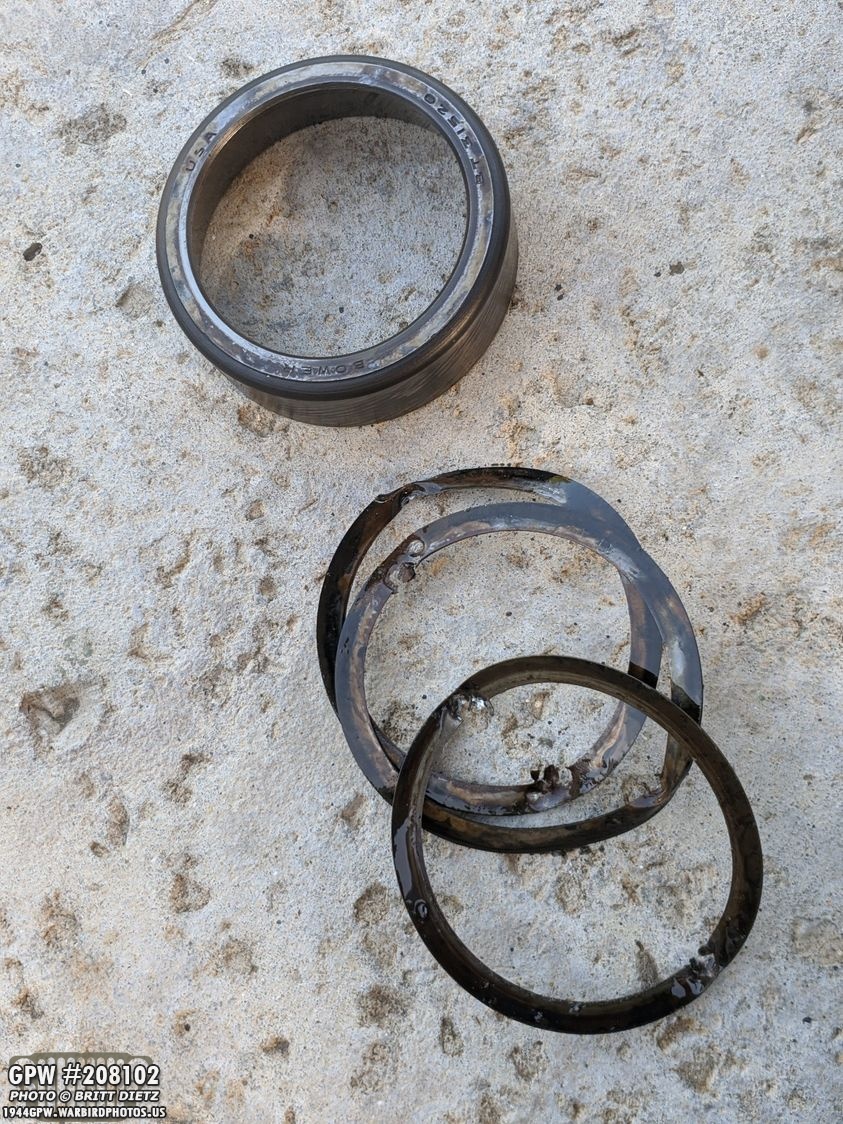
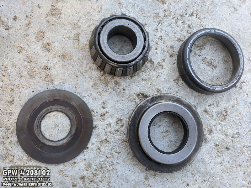
The inner bearing came off with the pinion when I drove that out, but the racer and shims were still in there, so here they are once I drove them out. I have replacement shims since these were destroyed super easy when being driven out.
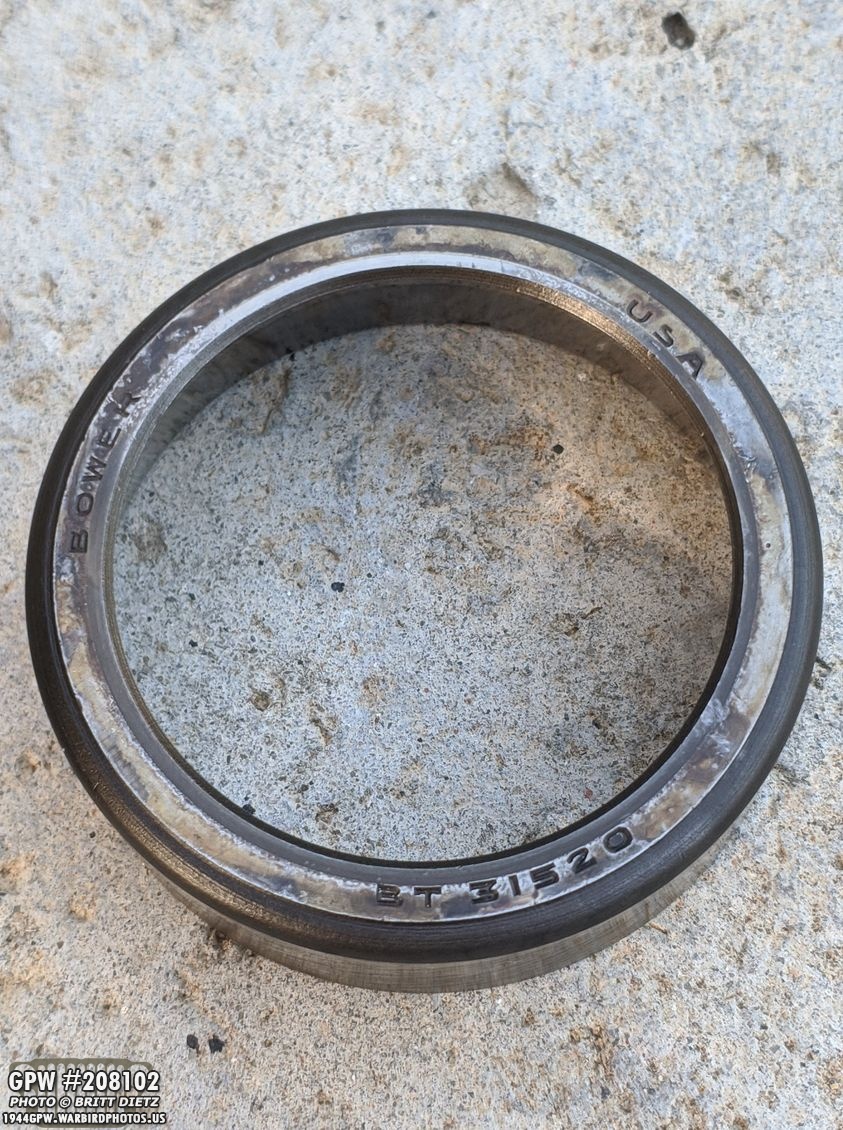
Here’s a look at the markings on this racer, which is made by BOWER.

After soaking the rear bearing/racer/slinger in parts cleaner, they turned out nice. I can reuse these.

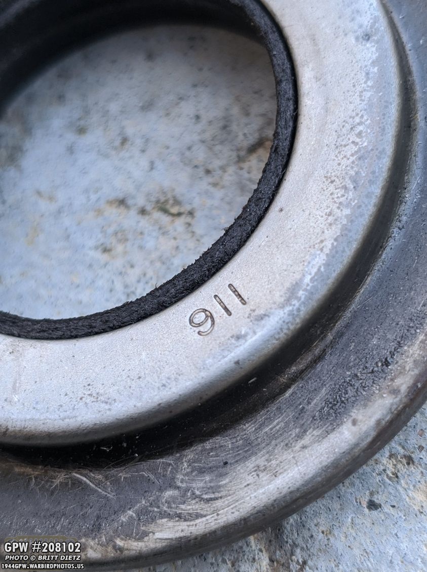
The slinger has what looks like TIMKEN (a main bearing supplier for WW2 axles) and the F stamp.

And here’s the markings that were on the rear bearing and racer. Both TIMKEN.

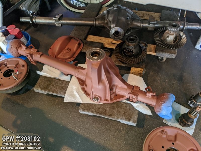
In a previous update, I took the drums from both axles to an auto store and had them measure the drums to see if they were in spec. The front axle were in great shape and in spec, but the rear drums were WAY out of spec. They should be between 9 and 9.015… then were 9.25! So those drums were not usable. Thankfully, I was able to trade for two GPW axles my friend Roger Smith had! They were brought by last week, and here’s how they looked.

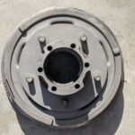
First up is the left side drum, which has left-hand threads (and marked with an L on all the studs!). Time to clean it up and check for markings!

After wire wheeling and sandblasting the entire drum, it looks nice and clean! Let’s check out all the outer markings!

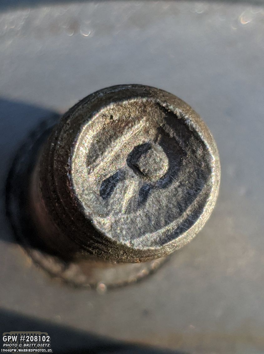
On one part of the outer lip, there is the drum part number of 24566. Also interesting is the Chevy Logo and a 3 on another part of it. After doing some research, I found that Chevy made drums for Ford for the Jeep and some trailers. Pretty neat to see!

But one of the cooler things that come about with the Chevy made Ford GPW drums is the fact they are dated! This screwed on data plate is actually a date! It goes Alphabetic Number for month, 1-2 digit day, and 1 digit number for which year in 1940 since these were only made during the war.G = 7/July27 = 27th Day 4 = 1944.So July 27, 1944! Only a month and a day after my Jeep was built!
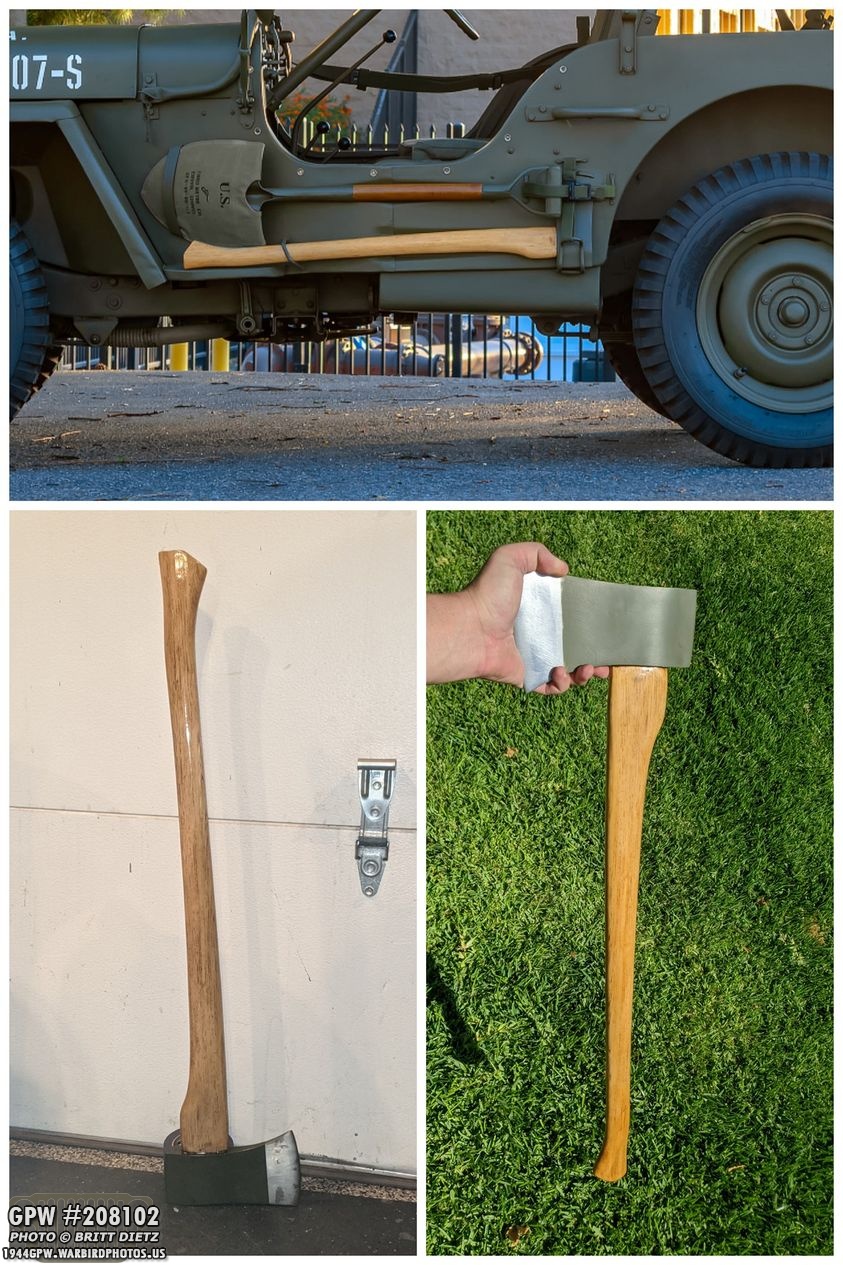
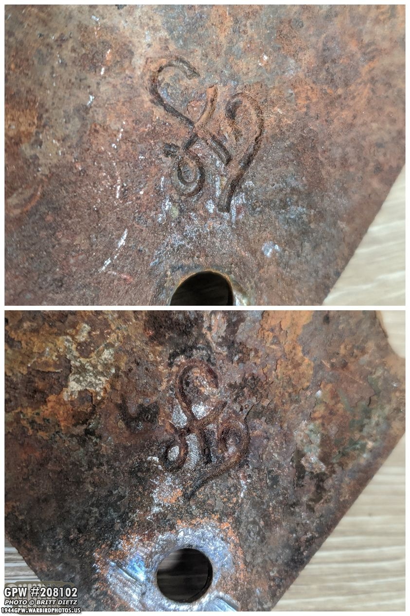
And just in case you didn’t think these were Ford drums, here’s the lovely F stamp under the feeler gauge slot.

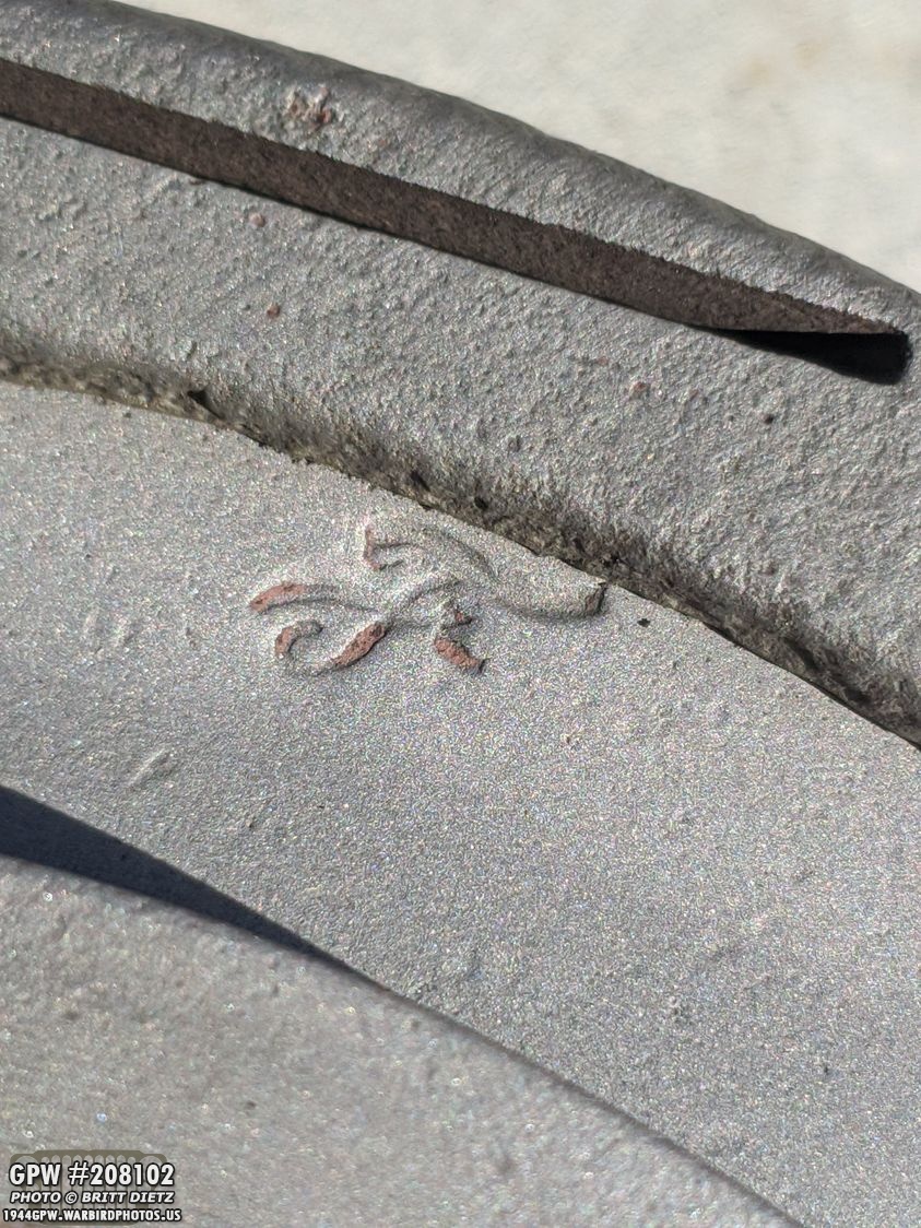
Looking inside the drum, there’s this interesting symbol stamped into the area between where the bearings and racers go.
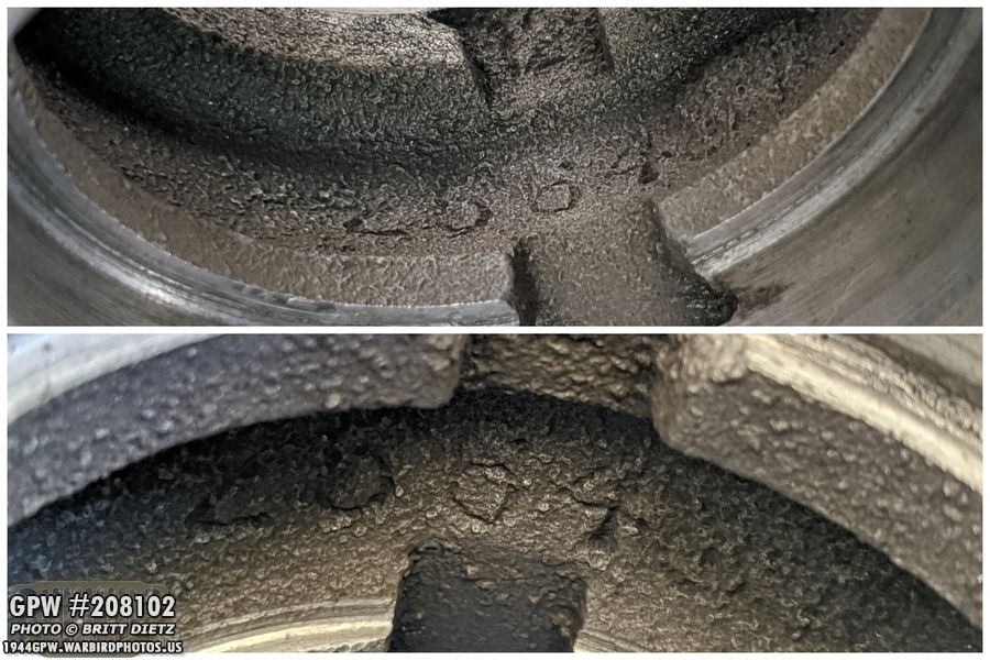
There’s also a number, possibly 256437?

Last step is to clean out the hub bolt holes, using a pipe cleaner. Lots of gunk in there!

I decided to try the right drum a bit differently. I let it soak in my ‘Bucket O Fuel’ for a few hours. Here’s right after I took it out. The paint is peeling away almost like paint stripper!

It still required a wire wheel and nylon wheel to clean it up, but it looks good. A final sandblasting this weekend and it’ll be all cleaned up. Now let’s check for the markings on this one!
First off, since it’s a right hand (driver) side drum, it has normal right-hand thread and is marked like the other side.

These numbers are not as clear as the other side, but it’s the same. 24566 part number, and the Chevy logo and a 1.

Here’s the date code for this drum, which is almost a year after the other drum. F = 6/June21 = 21st Day 5 = 1945. So June 21, 1945.

No F stamp that I can see, but there’s a faint V, or what looks like a V. After looking online, many people have posted that they have these Chevy made drums with one side having an F stamp and the other having an X in the F stamp place. So this might be one with an X that has worn away.

Inside, I see that logo and also a too-tough to read number.
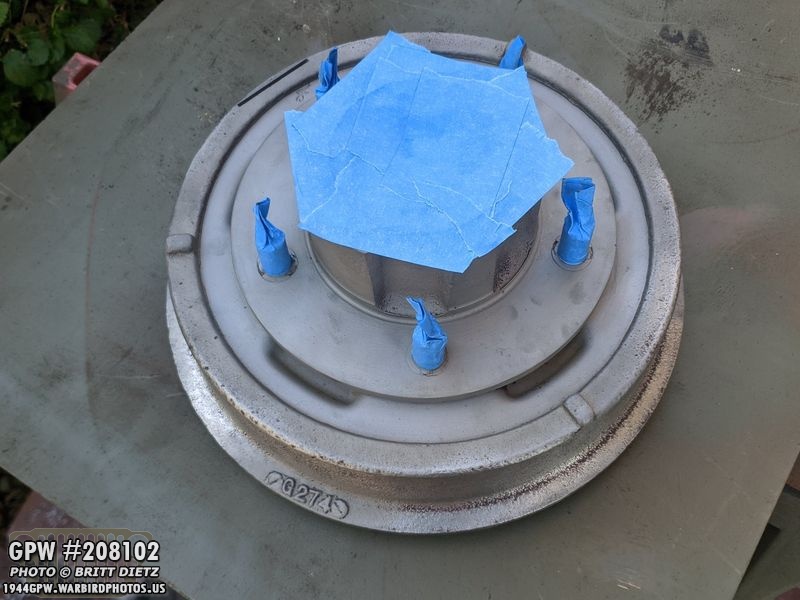
Switching back to the left (passenger) drum that’s finished being cleaned, it’s time for painting! I masked off the top area and the five studs.
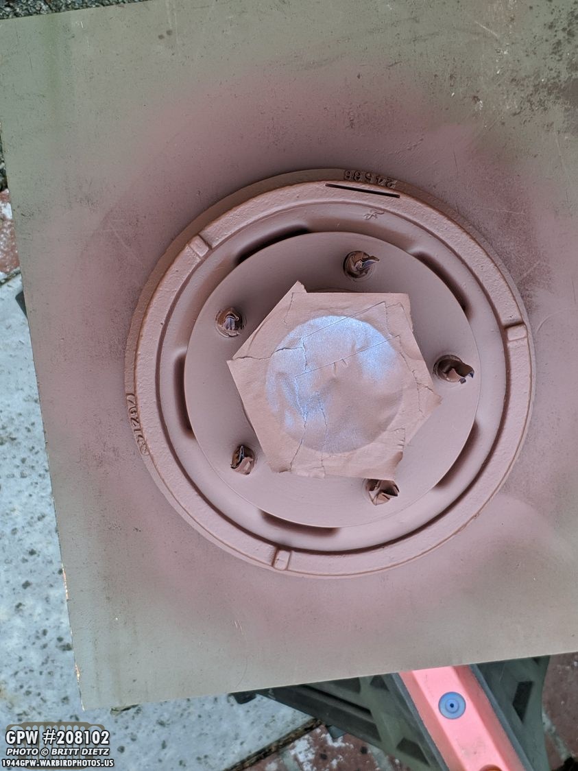
And then I hit it with Red Oxide Barrier III! That’s as far as I go with this drum for now! Next step with it will be when I mate it to the brake plate on the axle! Once assembled, I’ll paint the entire axle OD Green.

Here’s another look at that F stamp and the part number after the primer paint.

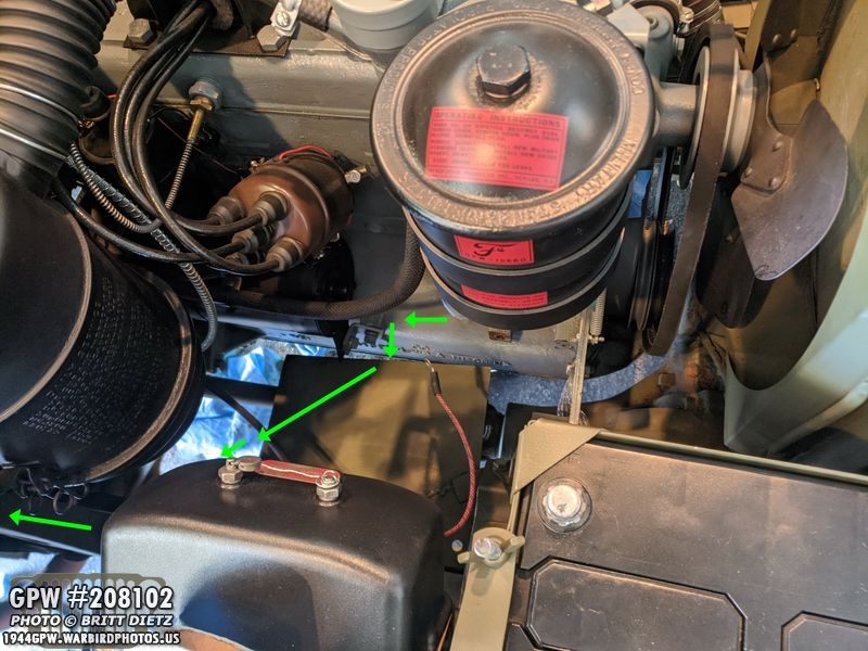
Now for the ‘simple project that turned into a multi-day expensive and loads of work’ project! Ever have one of those? I noticed that my fan belt wasn’t as tight as it used to be. Not sure exactly why, but when there’s only supposed to be a 1/2 inch of push on it, I was getting closer to 1.5-2 inches! So I decided to pull the alternator out further to tighten the belt. But, these CJ brackets were built so that the main bracket that goes from the front plate to the bracket that holds the alternator connects via the passenger side bolt of the water pump, which you can just barely see above the oil line (black).

Here’s another look. I took this after taking the bracket off the water pump bolt (red arrow) and moved it further away (in the direction of the yellow arrow) which tightened the belt. This got me to thinking… why do I have these CJ brackets on here? A normal generator bracket should work with my alternator!

So I ordered a correct WW2 style generator bracket (with spring) from &Ron Fitzpatrick Jeep Parts. It’s a 2 part bracket (technically 3) so that it can extend and contract based on how much you need to pull a generator away from the engine to tighten the fan belt. It has a spring to help keep the pressure on the generator.

I sprung for the F stamped one as it was the same price! It came pre-painted in a Ford Engine Gray color, but it wasn’t the same shade as my Ford Engine Gray.
So I sanded the brackets, bolts, etc and painted them with the VHT Ford Engine Gray I have. I also painted the spring which was OD Green.

While those were drying, I turned my attention to how I was going to mount this spring, since mine didn’t have one. I’ll get to that in a few, but first I had to take off this custom shelf bracket that was holding another bracket that was holding a third bracket that all held the bottom of the alternator. Confused? Yes, so was I when I first took this apart last year.

This bracket was on top of the previous image shelf bracket, which then holds another bracket (the next image will show them all together). But I’d forgotten there was an F stamp on this bracket. But it’s unlike anything I’d seen before. After trying to figure out what bracket this could have been, since Jeeps did not have alternators during WW2 and Ford stopped making Jeeps at the end of WW2.. what is this? I researched and discovered the reason I don’t recognize it is that it’s been HEAVILY modified. It used to the bracket that held onto the bottom of a generator in place of that shelf bracket on there now. Someone modified the heck out of it to work with an alternator. Sad day.

So, this is how all the brackets come together to hold the bottom of the alternator on my Jeep. It’s a total custom job someone did at some point. The bottom shelf bracket connects directly to the engine via the two bolts. Then who bolts hold the heavily modified original generator bracket and a secondary small bracket. Those both have holes on the end for a long bolt to go through. The long hole shaft at the bottom of the alternator goes on this long bolt where the green arrow is and allows the alternator to swivel left and right. Eventually one day I will get a correct generator bottom bracket and use a very long bolt to secure the alternator to it and the front engine plate, like the generators would be.

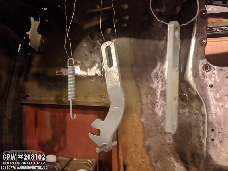
Here’s the new upper generator bracket arm all painted. I also removed the head markings off the bolt there (modern markings were on it). Time to install it! But I had to do some research on where it all goes.

So, typically the bracket is connected to the front engine plate via a large hole (red arrow) and large bolt on the end of the bracket which allows it to rotate from this spot. On WW2 engines (remember, I have a CJ engine), there should be a tab sticking out to attach the spring for the bracket, where the yellow arrow is. On CJ engines, there is no tab, and instead, a hole. Also, if you notice, the routing of my silver fuel line is not correct, it should be the route of the green arrows, so I’ll fix that while down there.
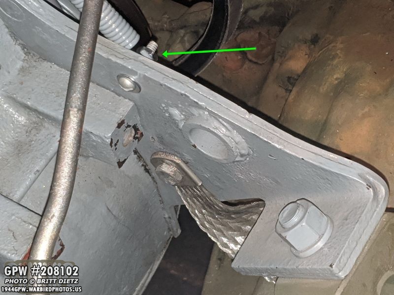
Roger suggested using a bolt with a nut… so I did just that. A round head slotted long screw with a washer on one side, and a washer and two nuts on the other side. BTW, that large hold above the silver bond strap is where a WW2 generator would be bolted in with a bushing inside.
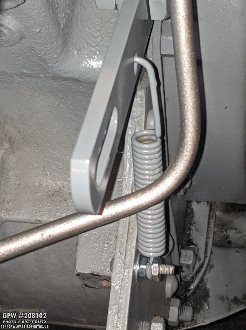
After installing the first part of the new generator bracket, the spring works perfectly with the screw and nuts! The two nuts help to keep it from slipping off, but with how much pull it will do to the spring, I’m not worried about that.
Before adding anymore of the bracket, I decided to move the fuel line. It should follow the route of the green arrows here. The fuel line ends at that large splash shield, and a flex line would connect it to another steel line that then goes up the toe board to the firewall mounted fuel filter. I took both fuel lines out to redo them and also change up that flex line. Instead of a single flex line, I had an inline fuel filter there with two smaller rubber lines on each side.

I also discovered that the fuel line needed to be clipped in a different location. Instead of on the alternator shelf bracket, it should be clipped to the same bolt as the generator bracket arm I’m installing. Also to note, the clip I’m using is F stamped!

It took FOREVER to get the lock washer and nut on that clip and generator arm bracket bolt. The clearance is SO tight in there, it’s quite the process and took me a ton of tries. Then it took almost as long to slowly use a wrench to tighten it. UGH! But it was all clipped now and the fuel line is in the correct route!

Here’s a look from the other side. You can see, there’s not much room to get that nut on there.

And here’s the new routing of the line. You can see where that line ends and the flexible line begins. I’ll cover that in a bit.

I then went back and installed the second half of the generator bracket arm, and used a long bolt with washers and a nut to connect it to the alternator! It was a perfect length I set it to, night and tight on the fan belt and not leaned out too far to hit the battery. On a generator, there would be no need for a long bolt like this, but that’s how it is for an alternator. BUT, it’s a correct style generator arm now, so that’s a plus!
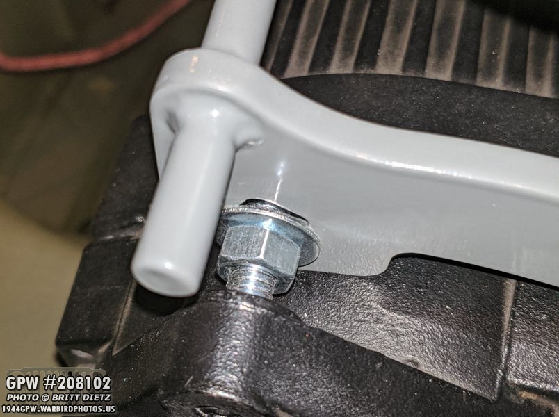
Close up look. The bolt is going into the alternator backwards. You can’t see the head of the bolt (on the other side of the generator bracket), but it’s the bracket head, a washer, the generator bracket, another washer, a nut to help lock it there, and then it goes into the backside of the top screw hole on the alternator. It’s super super secure.

And looking behind the alternator, here’s the routing of the fuel line.
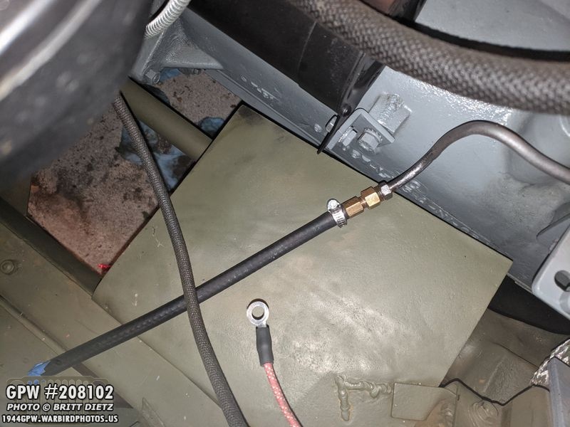
I wanted to replace how I did the flexible line with the inline fuel filter. I tried to shorten the length of everything so it’ll fit better as once I moved the routing of the fuel line, it was kinking the lines. So here I’m about to cut the rubber 1/4 tubing to then go to the inline fuel filter.

So I’m jumping ahead here, but this is how it turned out. From the fuel line to a connector (didn’t have another inverted flange female to push-on barb connector, so had to use a 2 step connector) to a small piece of rubber tubing to the modern inline glass fuel filter (always good to have one!), to another small piece of rubber tube to one of the single inverted flange (blah blah) connectors to the other fuel line that goes up to the firewall mounted WW2 filter (that doesn’t do the best job filtering the fuel, thus the need for this one).

With everything put together, I hooked the battery back up and fired her up for a test! Everything worked great. Fan belt was tight with only 1/2 inch of give, the alternator was solid without any vibrations, and the fuel was back flowing in through the lines!

But the $130 problem happened right after I stopped the engine. I noticed fuel spilling all over the splash shield in front of the starter. It was really coming out. I quickly put some shop towels to soak up the fuel till it stopped. What happened?! Bad connection? Rubber seal or the inline filter fail? No, those would be easy fixes…

It appears the steel fuel line, which (judging from the pitting) is original 76-year-old fuel line, FAILED. I cleaned up the pitting/rust and residual paint on the line before reinstalling on Wednesday to make it back to all-natural metal, and by doing that it must have caused some of the pitting to finally break through somewhere where the green arrows are. UGH! What does that mean? I will need to replace this fuel line. It’s dangerous to drive the Jeep with it leaking fuel like this, and there’s not really a way I can fix this. Plus that tells me there might be other areas on this line that are close to failing. So I had to put in an order for a brand new fuel line kit from &Ron Fitzpatrick Jeep Parts. About $130. I’ll replace the three other lines that are easy to replace in the engine bay just for safety when it arrives next week, but the bad news is that I’ll have to take the alternator, battery, etc all back out AGAIN! UGH.
So that’s it for now. Frustrating to have done so much and got it all back together only to find out that I have to take all that BACK apart to replace the fuel line. Sigh! So look for all that next week. That’s it for this week’s update! Till next week…(Also, I just realized, when typing this caption my fingers are in this shot. Doh! )