 Lots of little projects and two major ones!
After last week’s excitement with the hood numbers, this week was a lot of work on various projects. Starting with the painting of more axle parts, replacing some bolts with F bolts, fixing the horn wire, and figuring out issues with the fuel tank sender. Lots of ‘how tos’ in this update!
Taking the Jeep out for a spin this week around the neighborhood. Always a nice sight seeing the star on the hood!

Starting off this week with an order from Ron Fitzpatrick Jeep Parts. This week’s order includes axle oil seals, two replacement tie rods (F stamped), some F stamped bolts, a new knuckle seal kit for the front axle, and OD Green 33070 and Red Oxide spray paint. Let the projects continue!

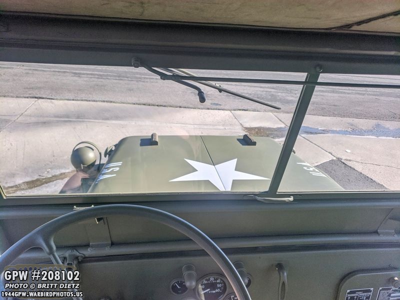
Another item I got this week from Germany is this awesome shovel cover. I’ve not liked the cover I’ve had as the straps were an odd forest green color. I saw this on eBay and loved the stamping. The shovel cover is a fantasy item, it was never on Jeep during the war, but I love the look of them and it protects the side of the Jeep from scratching with the shovel.
Looks perfect on the shovel, and the stamping adds that little extra to it! (Note – you can see the F stamp on my original shovel bracket)
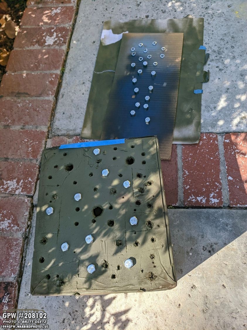
First project was to replace more standard bolts with F stamped ones. I’m slowly replacing what bolts I can on the Jeep, only the visible ones, with F marked bolts. Pretty much all bolts on GPW Jeeps had F stamps. Most of mine were missing, so it’s been an ongoing slow process. Here I’ve prepped the bolts, nuts, and lock washers for primer then paint.

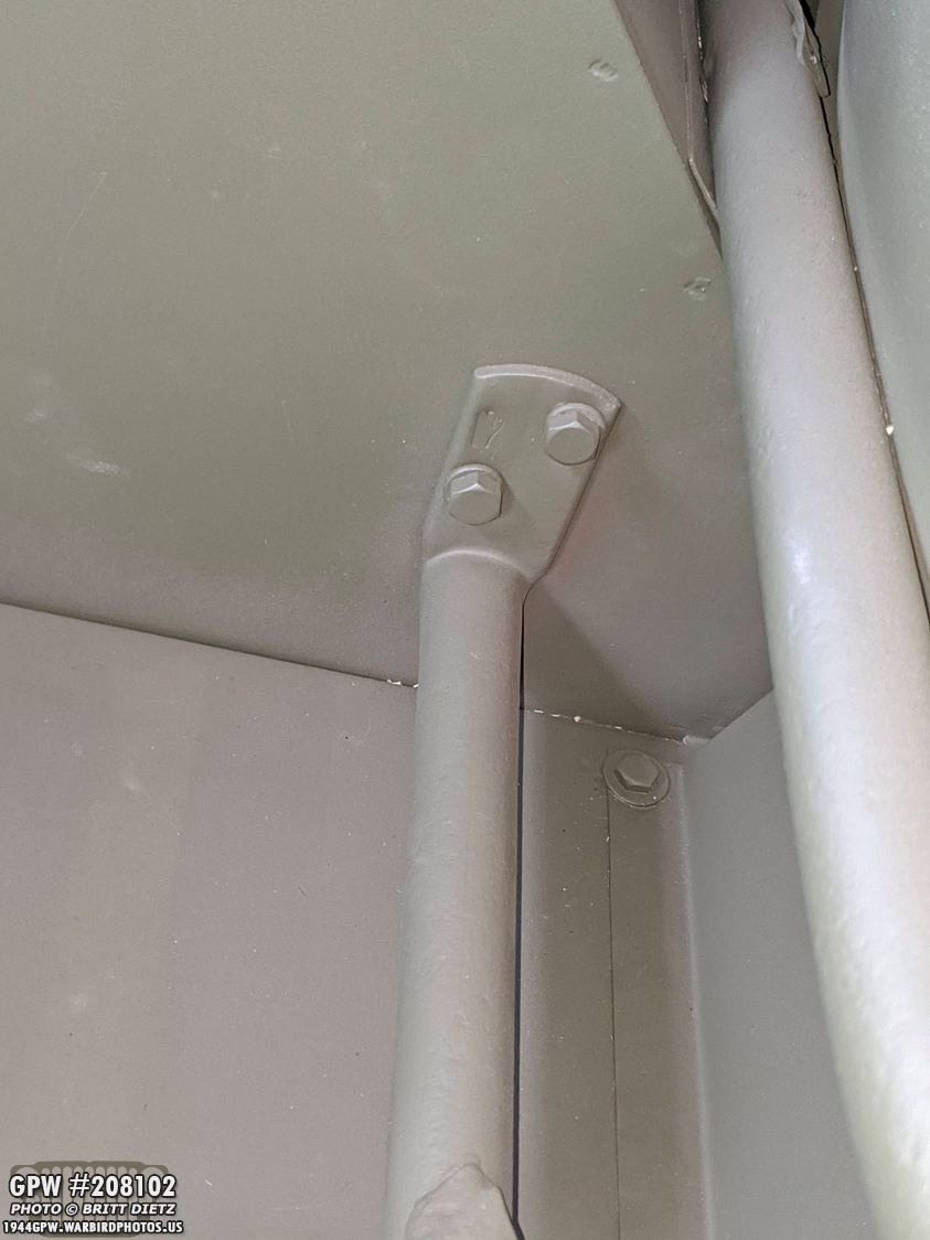
To start, I wanted to replace the lower bolts on the rear top bow brackets with F stamped ones.

Replaced! Just needs some touch up paint! I also took the time to sand some areas that might be scuffed or cracking.

And now all painted! I did the same with the top bow on the other side. The little details add up! Eventually, I’ll get F stamped top bow brackets.

I’ve been wanting to replace the bolts holding the windshield bracket with F stamped ones as they are very visible.

Both bolts replaced! (chain is wrapped on the thumbscrew to get it out of the way)

And on the other side, replaced but I haven’t touched up the paint yet. Both of these bolts just happened to line up in their orientation. Wasn’t intentional!
Next up was the footrest bolts that connect to the wheelhouse.

Much better! And you can see the F stamp on the original footrest.

Same with the other side. Not sure why I originally put the lock washers on the bolt head side.

Much better! Just needs some paint touch up!

Another quick project I did was add the footman loops to the bottom of the passenger seat. These loops are intended to hold a strap that holds a folded canvas top when not being used. My original passenger seat had the screw holes for the loops, but was missing the loops themselves. Here they’ve been freshly painted.
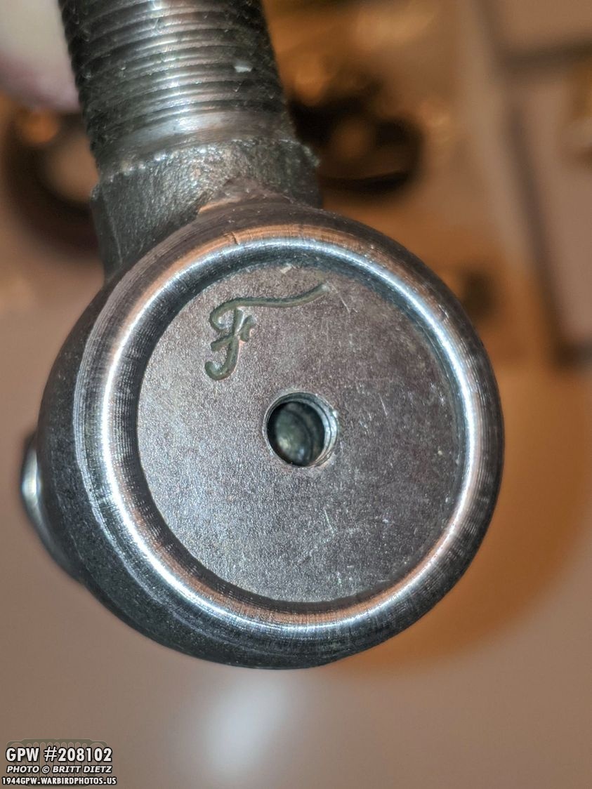
Switching back to the order I got from Ron Fitzpatrick Jeep Parts, here’s a look at the F stamp on the repro tie rods.
They fit perfectly in the original steering rods (left and right threads on each side)

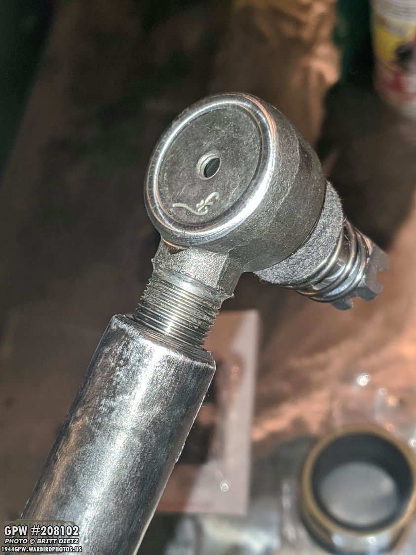
Here’s a look at the repro (left) and the original (right). This is one of the originals that is going to be replaced due to the top cracking open.

Stamping wise, they are a bit different. The original (left) has FORD and USA with a C on it. The repro ones just have a Ford F stamp. Since I’m replacing two of the tie rods, it’ll work as they will match.

Another item I got this week was a new knuckle seal kit. This is a modern kit and the most widely sold. It replaces the original knuckle seal brackets. I wasn’t too keen on this new updated look, as it would be clear I was using this new kit. But someone on the G503 forums mentioned a method to use the original brackets to make it look correct. This shot shows all the pieces, for one side, in the kit. A rubber seal, felt gasket, and two plain metal brackets.

First, take your original knuckle seal brackets and split them apart. I’d already done this and removed the original rubber and worn away felt. They are a bit tough to get apart, I found using a little screwdriver to slowly get the tabs out of the small holes worked best.
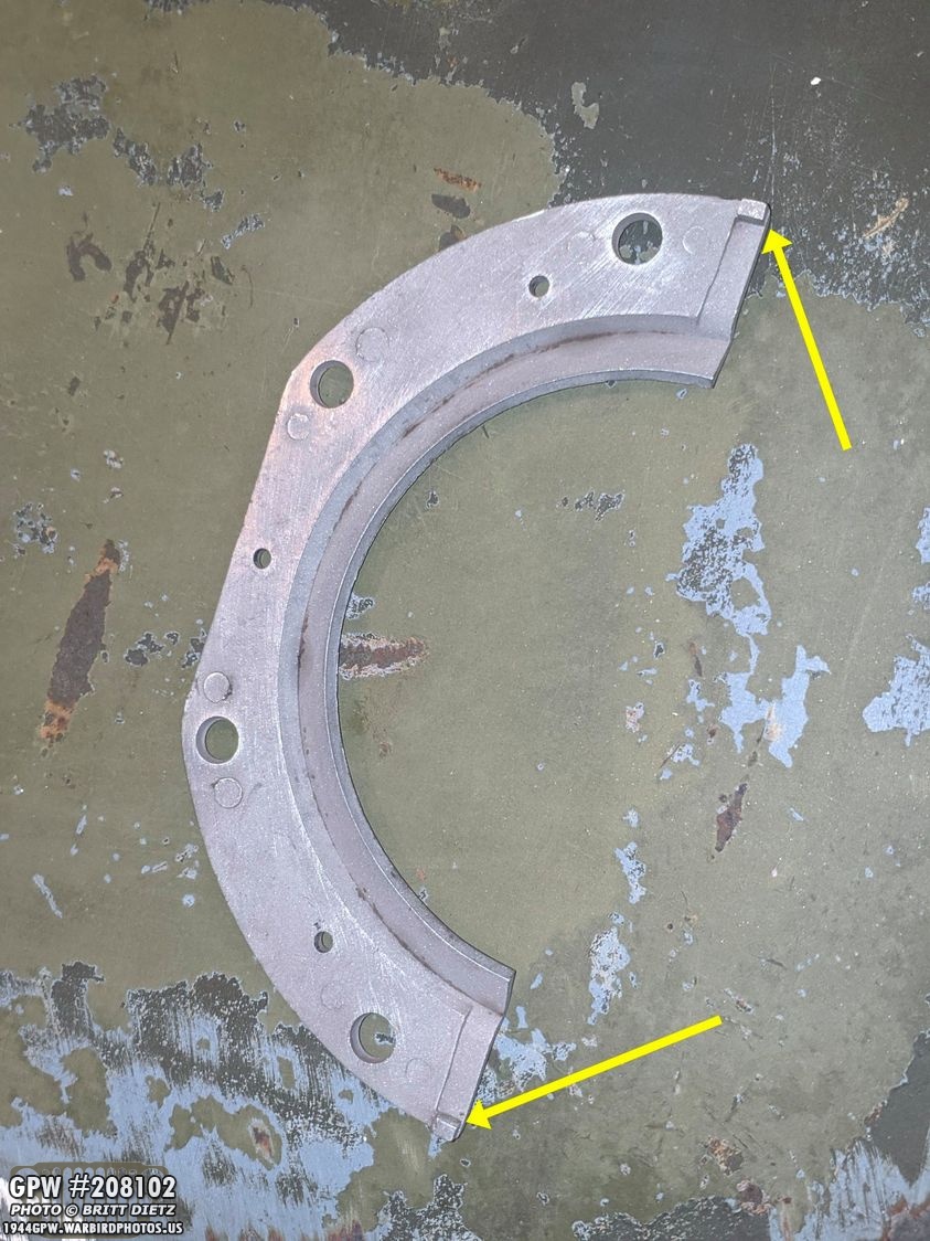
Now, take the outside portion of the original bracket, which for me is this piece without the tabs. I’ve heard that some people’s outside bracket might have the tabs, not the holes like this, so if that’s the case just file off the tabs. You then need to file off the cap tabs (yellow arrows)

I’ll demonstrate how it’s installed, but you don’t want to permanently install these without the kingpins being on the knuckle housing. First, take the rubber ring from the new kit and place it with the gold side (shown here) facing down.

Here’s the rubber ring installed.
Next, put the felt gasket above that.

Now take the outside halves of the original knuckle brackets and bolt them on. Looks original with the new, more improved, seal and gasket! A quick way to make the modern seal look original. I’ll probably fill in the holes on the original brackets to make it look like there’s tabs in them from what would have been the other side.

Now to the axle progress for this week! This is an old photo from many months ago when I was just starting to work on them. For those that are new to the page, in short, my Jeep had the wartime axles replaced with CJ2 axles sometime in her life. I was given a pair of wartime original GPW axles that I’ve been slowly restoring over the last few months.

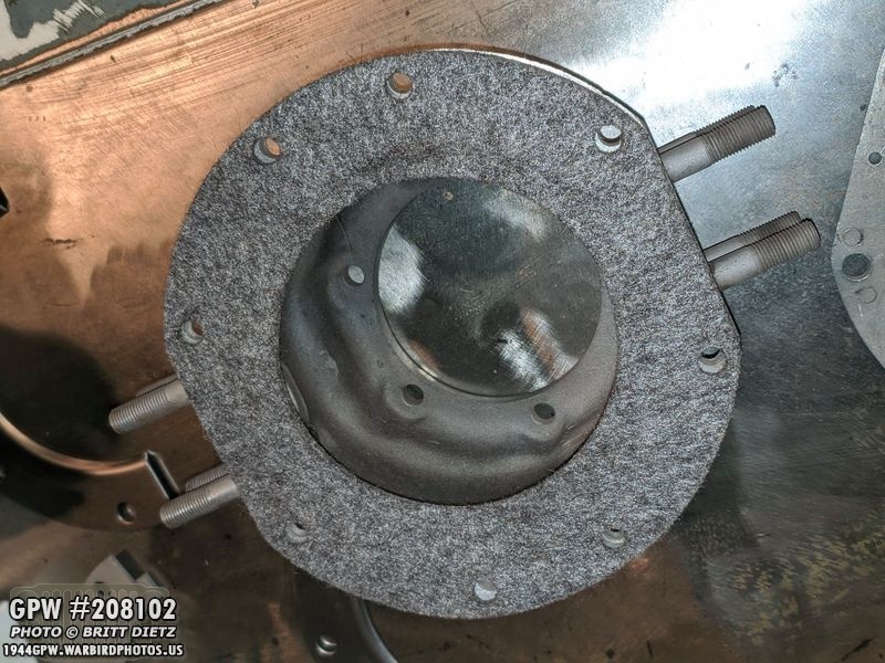
Two weeks ago I learned that my rear axle drums were out of spec and therefore unable. So I stopped work on those drums (getting a pair of original replacement drums soon!) and continued work on the front drums which are still within spec. I’d been meaning to get the two bearing racers out of the drum but hadn’t gotten to them. It took a lot of effort to get them out, they did NOT want to move. But, eventually, I was able to wiggle them out with a drift and some careful pounding.
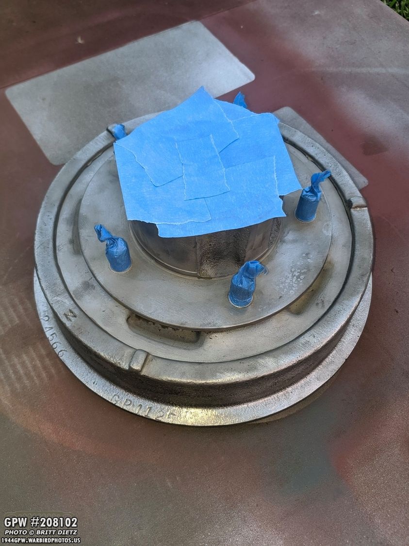
With those out, it was time for painting! Here the main opening has been masked along with the lug nut bolts.

And both axles painted with red oxide primer from Ron Fitzpatrick Jeep Parts! With warm weather out, but the time I finished painting the second drum (left, still wet), the first drum I had painted was pretty much dry. Love this Red Oxide spray paint! I put two coats of the primer on. The OD Green will not be added until the axle is put together.
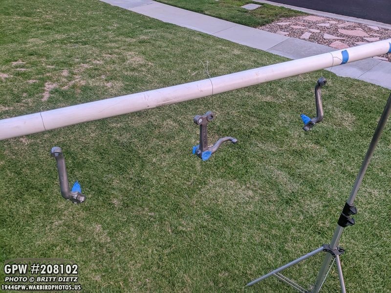
Painting the two steering arms and the bell crank. Before…
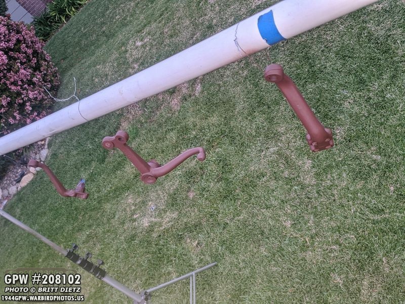
After! Since I got some paint in a few of the holes (which are where the wire holding them up goes through, the rest are plugged with paper towel), I used pipe cleaner brushes to get all the paint off inside.
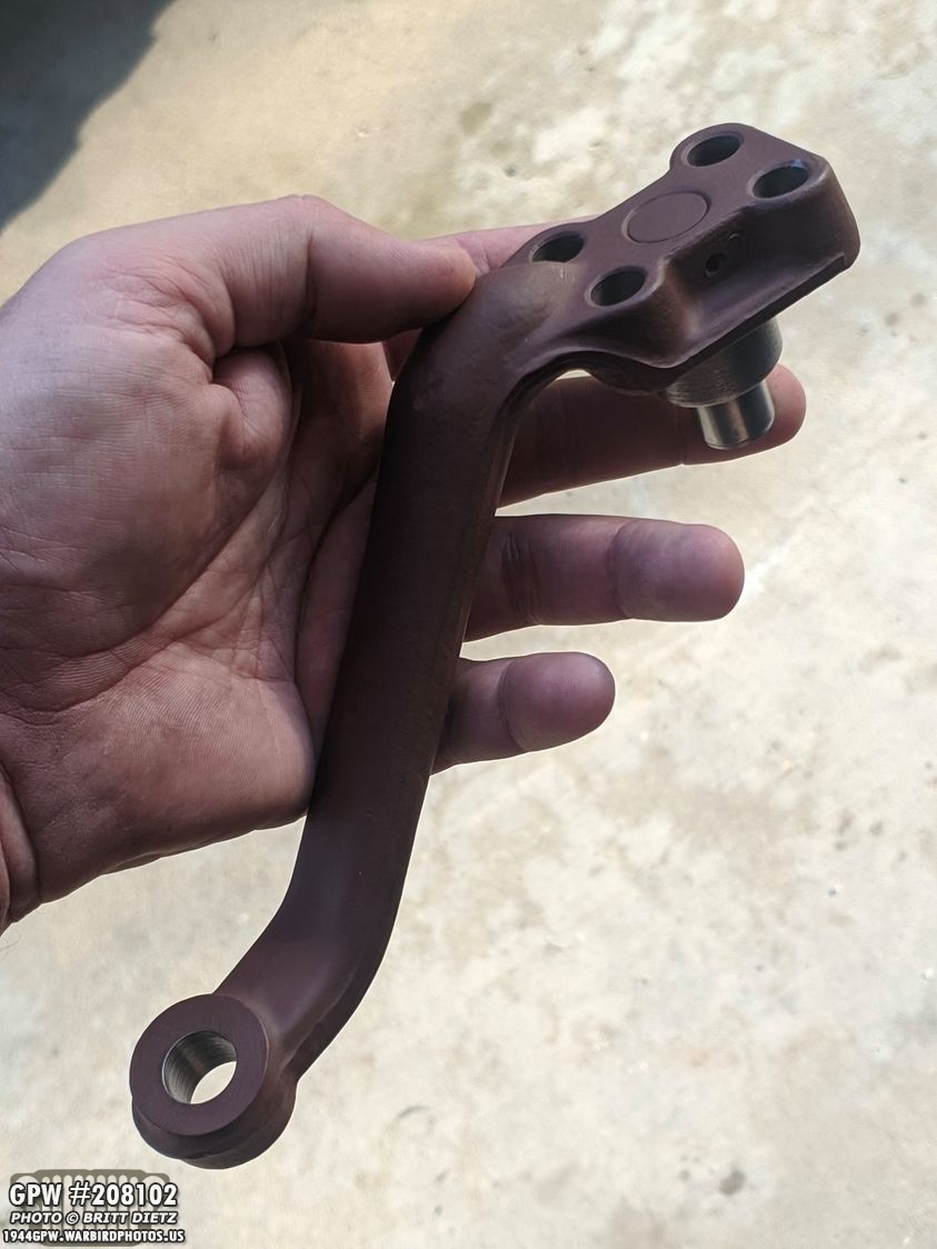
All ready for reinstall back on the axle when it comes time!

I also primered the steering rods, which brought out the original Ford stamping.
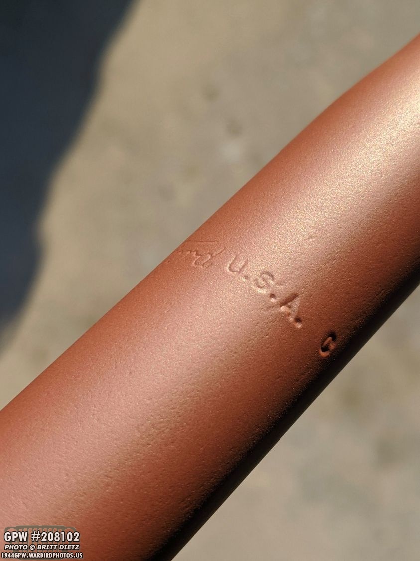
Just like the Tie Rods, it has FORD, USA, and a C.

And I primered the four clamps for the two steering rods.

So, moving on I decided to tackle three large projects I’d been putting off for various reasons which I’ll explain. These were some time-intensive projects, so I’d never gotten around to them. PROJECT 1: Passenger step to fender connection. This one has been an eyesore for me for almost a year now. Since the MD Juan tub didn’t line up perfectly, it also meant the passenger steps to fenders had some alignment issues. I was able to manipulate the driver’s side fender and get it lined up, but that meant the passenger side has always been misaligned (shown here).
What I needed was a large punch to help align the holes. I finally went out and got one, and was able to get one of them aligned, which meant I could then get the other bolt locked in. That held the fender in place so I could take out the punch and put the second bolt in. Because the first fender hole was slightly ovaled, I decided to use a second larger washer just in case.

SO much better! Nice and tight now, no gaps or fender holes showing! Big relief to get this done! After some touch up paint over the bolts it’ll look perfect.

PROJECT 2) The Horn contactIf you remember back in February when I had my Jeep in Old Town Orange, my horn contact came off and caused the horn to short out when turning right (making the horn honk when the steering wheel was turned right). I parked and removed one of the connections to the horn which stopped that (it was real annoying). Since then I’ve not fixed it so I haven’t had a horn.

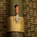
This is the problem right here. This shot is from last year when I first soldered the wire to the brass contact ring. The wire is coming out from inside the inner steering rod. From this point, it goes up the rod and out the top where the steering wheel is attached and there’s where the horn button is connected to the end (I’ll have a full diagram in a few photos).

That connection had come off back in January, as you can see here with the wire (above the brass ring) separated from the solder. This is VERY common on Jeeps, and one of the worst designed things. There’s a million ways I could think of better ways to do this. The solder doesn’t like brass, so you’re relying on some flux that isn’t thick. When it broke in January, I had to solder it like this (which I showed in a weekly update) working in between the fender and manifolds trying to solder. It was tough, and I knew it would break again.
Since it had broken a third time, I wanted to figure out how I could make it a bit more secure. I didn’t want to have to take out the steering rod and steering box as that’s a huge project that requires removing a LOT of things on the Jeep. So, how could I make it more sturdy without removing everything? Well, one thing that worked in my favor is that the brass ring wasn’t permanently connected to the red insulated ring, so I could slide it off. Once on the insulation, it stays on, but I can slip it off. So, with that in mind, here was my plan (next photo)…
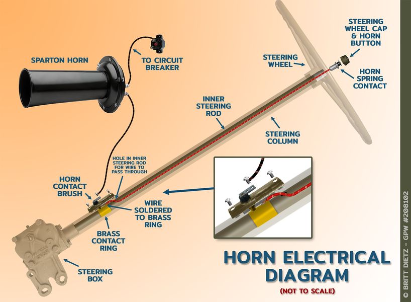
Here’s how the horn system works. My plan was to take off the steering wheel cap and button, and then pull out the horn wire with the horn spring contact at the end. This would be easy since the other end of the wire was undone. I would attach a wire to the unsoldered end of the horn wire when pulling it through, so I had a leader wire still going through the horn. I’d then take off the steering wheel and pull off the outer steering column. In doing that, I could slide the brass ring off the inner steering rod all the way. I’d then solder the wire on REALLY well (with new flux) and then slide the ring back on with the soldered wire. But how do I get the wire back through the inner steering rod?

Well, here’s a look at the inner rod without the other column after I slid off the brass ring. You can see the red wire I have as a lead wire when I put the ring, with the soldered wire, back on.

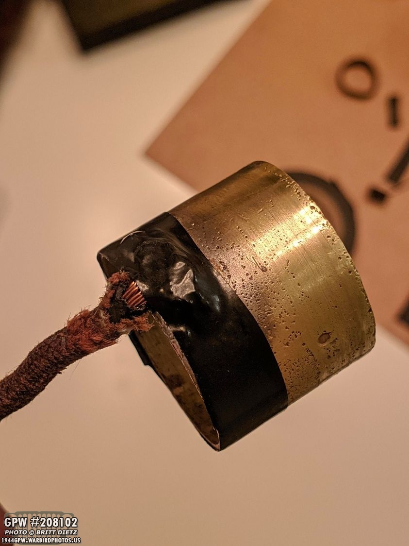
Here’s a look at the brass ring. As you can see, there’s hardly any flux for the solder to grab (and there’s a small crack).

So I used a Dremel to remove the old flux, and I shaved down a ‘pocket’ for some new flux. I used an instant soldering kit, which has flux in it. You paint it on and heat it up with a torch. When you’re done, it’ll look like…

This! That’s a LOT of flux/solder for the wire now! And it repaired the crack.
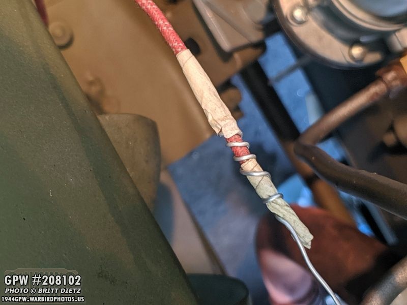
I didn’t get a photo of the soldering, but here’s after soldering. It was on there really good. But, as an added safety, I decided to use some electrical shrink wrap that I carefully sized so it wouldn’t get in the way of the steering contact bracket brush. This should help keep it in place for a long time, along with the much better solder. Now, how do I get this back on?
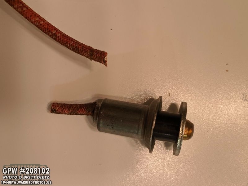
This is how… I had to cut off the spring button end of the wire. I’ll resolder this back together once I get the wire back through the inner steering rod and out the other end.
Looking inside the Jeep, you can see the red leader wire coming out on this end.
It turned out that the red wire was too thin, and I had all sorts of problems with it. So I replaced it with thicker wire (seen here, silver). With the brass ring back on the inner rod, it was time to feed the wire back through. With the cut off end of the horn wire, I carefully wrapped the leader wire around it and put some thin tape around it to keep it there. You have to be very careful it’s not too thick or it won’t fit through the small hole on the inner steering rod.
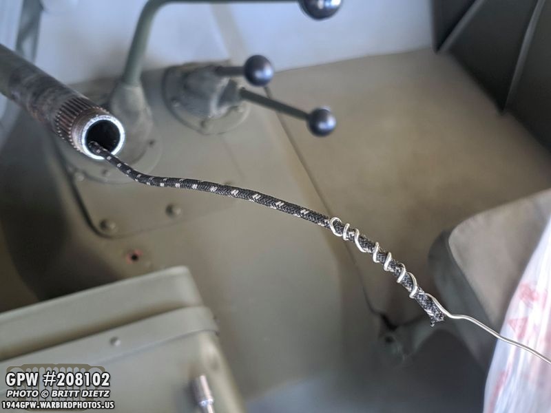
That’s when another issue came up, the horn wire wasn’t quite as long as I thought and didn’t come all the way out of the inner rod. DOH! So I reversed the process and pulled the horn wire back out (it’s still soldered to the brass ring) and I added about 4 inches of spare wire I had from custom wiring I did on my wiring harness for the push-button start. Then I reattached the silver lead wire and pulled it through to get this! Perfect!! Now to re-solder the button end!

I cut the new wire I added shorter, and was able to much easier solder the two wires together. That solder place sleeve is shrink wrap that, after soldered, I heated for a nice tight (and protected) bond. No exposed wires, and it’ll all be hidden in the inner rod under the button. But, with ALL this work… does the horn work?

I carefully put the outer column sleeve back on (shown here) and gently put the steering clamp back on.

Reattached the horn and the horn wiring… then put the contacts on the battery. Moment of truth… went over to the steering wheel and hit the black button… HONK! Yay! Next step was to turn the wheels and hit the button to make sure it makes contact all the way around and the wire stays soldered on… HONK, HONK, HONK! It works! I saved myself a LOT of time doing it this way. While it still took hours to do, it would have taken many more hours removing the header pipe (breaking seals requiring new ones), heat shield, etc. I’m hopeful this will mean a lasting horn connection for a long time.

Finally, PROJECT 3) The Gas GuageSince I put my Jeep back together, my gas gauge doesn’t work. It’s a new gauge (the original one was busted, no continuity in it) and a new gas sender (the original one was busted as well, no resistance). In testing, the new gauge and the new sender worked great, I was able to get it to read E to F when moving the sender arm. But when it was all installed and gas put in, it’s read empty for almost a year now.

Here’s a look at the original sender and gauge (left) with the new sender and gauge (right). At the end of the sender is the large float. This float is supposed to stay on top of the fuel level, and where that arm is positioned causes an electrical resistance which the gauge reads. The difference in resistance (the rotation of the arm with the float) translates into the fuel level indication.

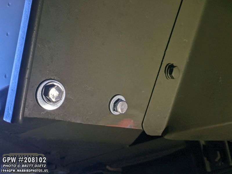
And here’s how the sender looks connected to the fuel tank. The large cap is the main fuel cap where the fuel goes in. On the right, with the wires, is the sender with a protective cap on top. Typically, there’s just one wire, but many people (myself included) like adding a second wire for better grounding. This small wire discreetly connects to the nut side of a screw that holds one of the footman loops on the side of the body. Grounding is very important for a gas gauge that works, so this is a way to ensure a good ground.

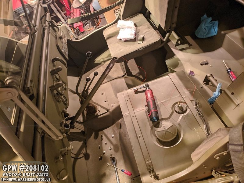
This is why I’ve put off, for almost a year, trying to fix this issue… the gas tank shield and the driver’s seat. They took me almost 2 hours to install when I put them on. Again, it’s an MD Juan body tub issue of alignment, and the seat fights with the gas tank shield and vise versa. Heck, the seat fights with itself not wanting to line up with the body tub mounts. I dreaded taking the seat off and knew it’d be a long project. But, since I’m stuck at home and needed more Jeep projects to tackle, why not this? So I took the seat off and the shield
Once I took off the seat, I could get to the sender. First thing I did was take the sender out of the gas tank, turn on the ignition switch, and move the arm. It worked still, the gauge went from E to F and back as I moved the arm. Okay, so it’s not a grounding issue or something busted. I put it back in the fuel tank, and it registered empty. Whaaaaa? So I took it out again, and this time I decided to try something different in how I put the float into the tank.

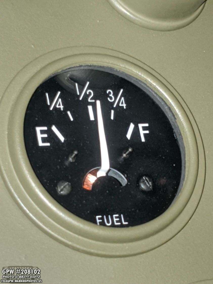
Instead of putting the arm and float down into the tank (red arrows), I tried to come in at an angle so the float was automatically on top of the fuel line (green arrow). That worked! It was showing just above half a tank! YAY! But why was it not working before? This made me nervous that it would stop working once I took all the time to reinstall the seat and gas shield. I needed to test more.

Test 1) Is the float sinking? Does it have a hole and sinks? I shook the sender right after taking it out of the fuel, no liquid inside. That’s not it. And it stays on top of the fuel level when put there. Test 2) Is there something wrong with the arm? I noticed there seems to be some slight resistance on the arm when moving the float up. It wasn’t super easy. So I put some WD40 on the arm (red arrow). I then took a tray and put about 3 inches of fuel in it. I put the float on top of the fuel, it floats. So then I pulled the sender away from the tray, and the float stayed on top of the fuel. Great! So then I moved the sender closer to the fuel, and the float sinks and bottoms out. Whaa? After trying this a few times, I realized that there’s too much resistance in the arm. It won’t allow the float to, well, float! But gravity and the weight of the float is enough to keep it floating when the fuel level goes down. Issue solved, it’s a BAD sender.

Thankfully, Ron Fitzpatrick Jeep Parts’s customer service is amazing, and they are sending me a replacement sender (arrives tomorrow, so look for my results next week). For now, the driver’s seat and gas tank shield will remain off until I can get the gauge working. But it’s one step closer! At least the horn is working and the fender/step alignment fixed. 2 out of 3 big projects done isn’t bad!

Also, I did mention that this week I’d be restoring an original medical kit. I will cover it next week as I wasn’t happy with the color I painted it, so I ordered the correct paint and it’ll be here tomorrow. So next week I’ll cover the complete restoration.

So that’s it for this week! Lots of projects and busy work. Next week looks to be packed with some more fun (and not so fun) projects. It’s good to have a Jeep to keep me busy during the stay-at-home orders. Till next week, stay safe!