 Valve Adjuster Screw Replacement
Following up with the perfect timing of the engine, I decided to finally get to replacing all the valve adjuster screws. What started as a one-day job turned into a 3-week project! This will be a multi-part update. This first part will look at the actual replacement of the adjuster screws and valve adjustment.
I’m very behind on updates; in fact, there are about three weeks’ worth of updates I need to get out covering June and July. It’s been a busy two months with the Jeep! So, let’s dive in with the first project: Value Adjusting and how that went from a one-day project to a 3-week project!
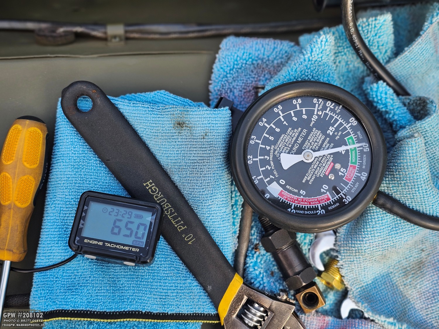
Last update, I talked about perfectly timing the engine with a vacuum gauge and a tachometer. With that gone over insanely better than I could have imagined, I was looking at the next project.
The Jeep was running better than I felt it ever had (ironic foreshadowing of future updates coming soon), so I decided that before the upcoming 4th of July parade in Corona, CA, I wanted to do the one thing that I’d been putting off for years: replacing the valve adjuster screws.
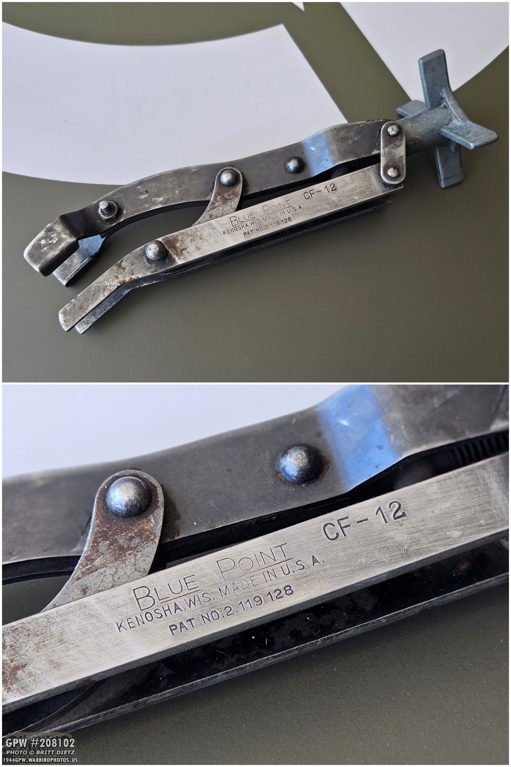
Anticipating this, I went on eBay and found a vintage valve spring compressor tool. This Blue Point CF-12 is considered period-correct for the WWII style, and looks exactly like the one in the Jeep Technical Manuals.
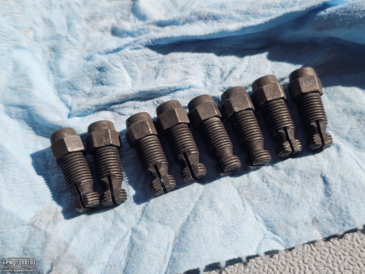
And, I also got a set of NOS (New Old Stock) valve adjuster screws. Let’s pause for a second and explain what they are and why they need changing… The valve adjuster screw threads right into the top of the tappet inside the block to make direct contact with the bottom of the valve stem. It exists so you can dial in the precise valve lash (gap) needed to handle normal engine wear and heat expansion. As the camshaft pushes the tappet up, the adjuster screw physically pushes the valves open, and having that adjustable gap ensures the valves still close and seal completely tight when everything heats up.
The problem is that over time, the top of the adjuster screw heads can get worn and ‘cupped’ from constantly hitting the bottom of the valve stems. This can cause a tapping sound from the engine. This tapping sound can be loud. Most people just ignore it, but it always bothered me. I’ve adjusted the valves twice, and the tapping is still there. So, it was time to replace the adjuster screws.
The problem is that over time, the top of the adjuster screw heads can get worn and ‘cupped’ from constantly hitting the bottom of the valve stems. This can cause a tapping sound from the engine. This tapping sound can be loud. Most people just ignore it, but it always bothered me. I’ve adjusted the valves twice, and the tapping is still there. So, it was time to replace the adjuster screws.
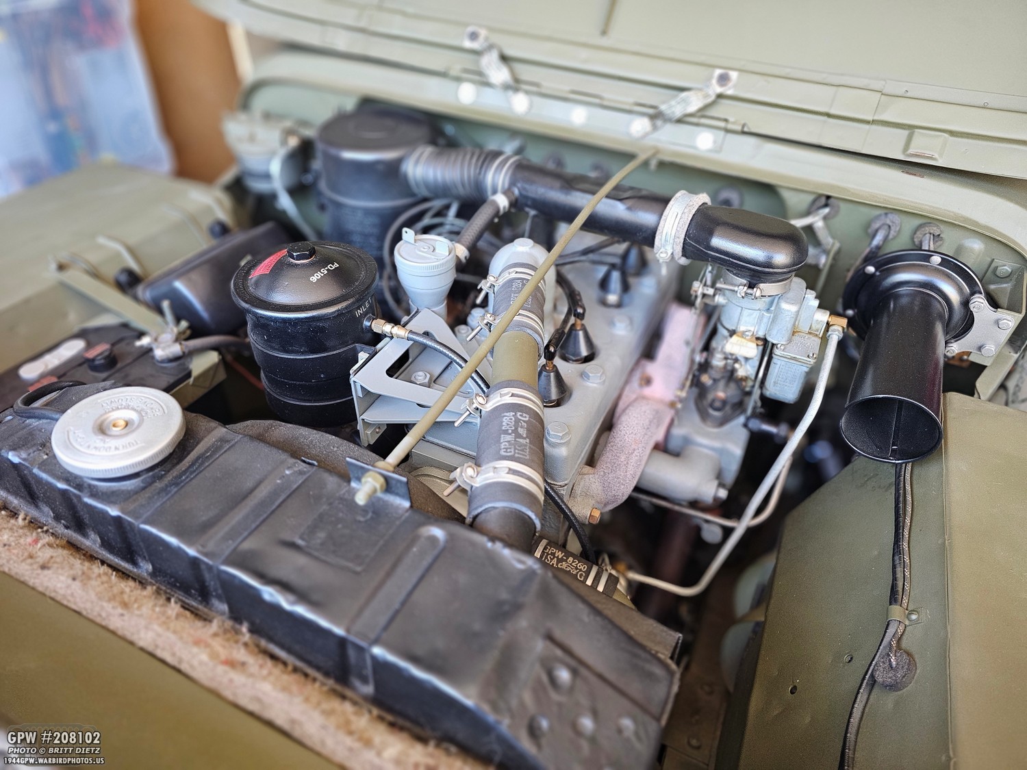
It’s not a quick task; it requires a lot of things removed, and a lot of patience as you adjust the screws. Originally, the plan was to spend a day replacing the screws. I’d take the various items off the engine, open the side valve door on the block, compress the screws (lifting the valve up), unscrew and remove the adjuster screws, put the new ones in, adjust the valves, and then reinstall everything back on the Jeep. Not too difficult, but not a one-hour job for sure. So I’m going to take you through the entire process, from what you need to remove, how to access the adjuster screws, what I realized wasn’t going to work, and how I ended up getting through the whole thing.

So, we’re going to need to remove the front driver’s wheel. Do you have to? No, but it’s going to make your life so much easier. So get the Jeep up on jack stands.
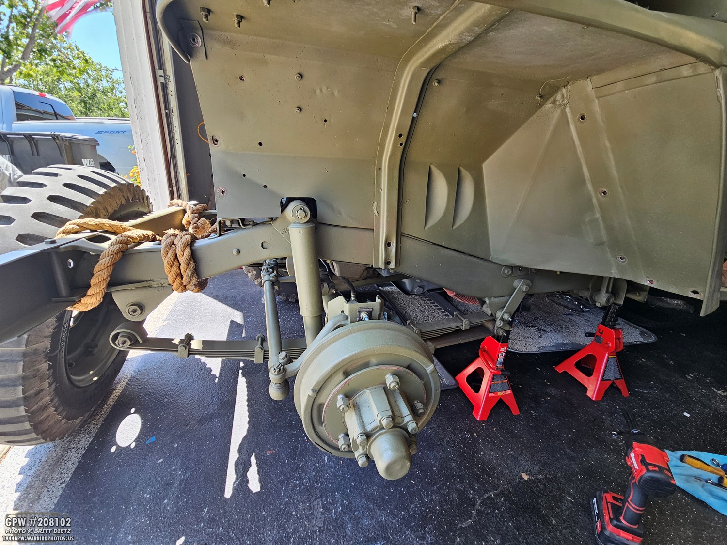
Remove the wheel. While it’s removed, I think I’ll do some paint touch-up work on the frame, wheel hub, fender, etc.
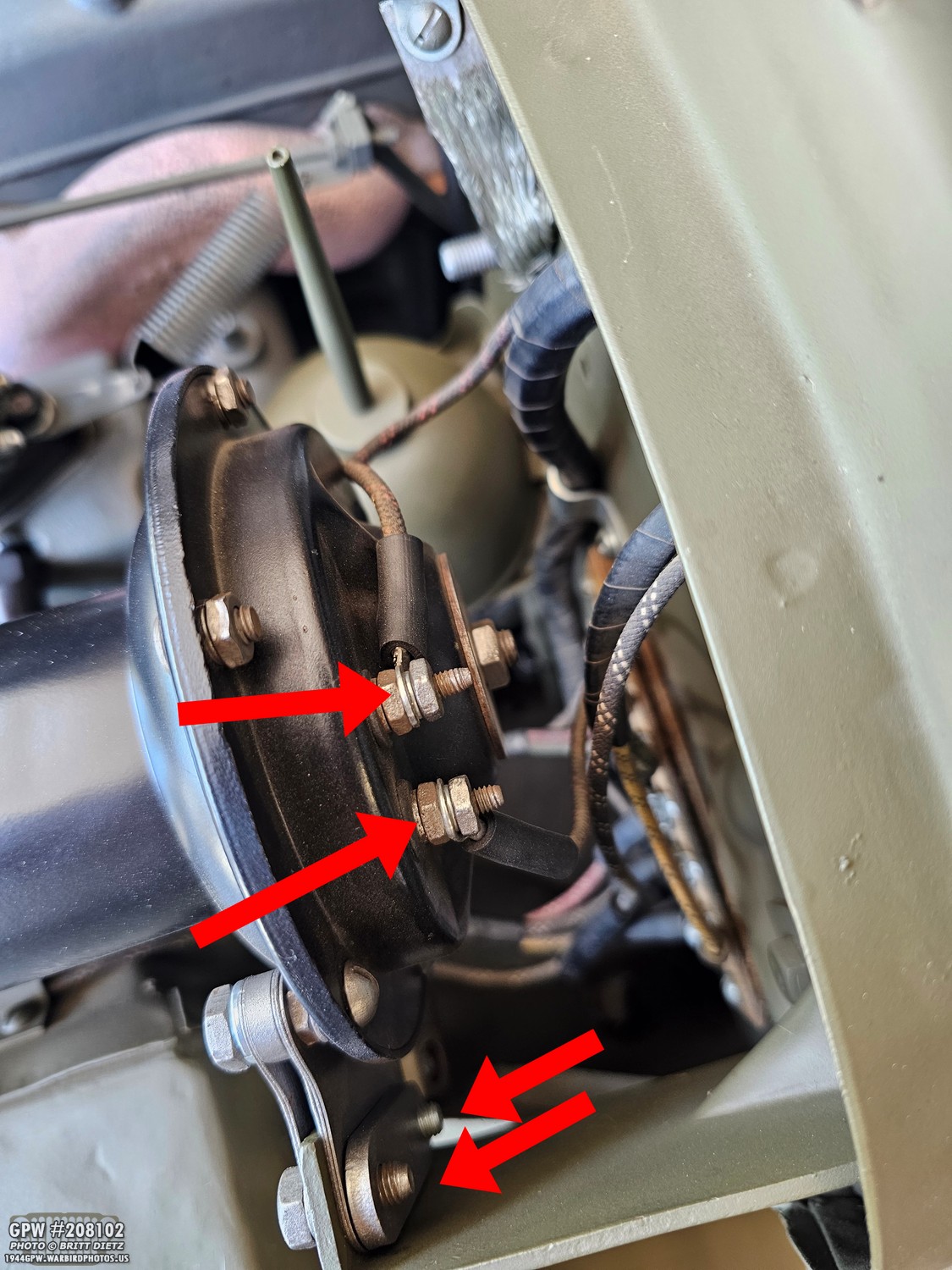
Next, remove the electrical wires on the back of the horn (make sure the battery is unplugged). Also remove the two bolts holding the horn vibration damping bracket out so you can remove the entire horn and bracket assembly from the Jeep.

To give me even more room, I removed the screws for the oil can holder and took that entire thing out. Also, don’t forget to unplug the fender blackout electrical connector, as we’re going to be removing the fender in a sec.
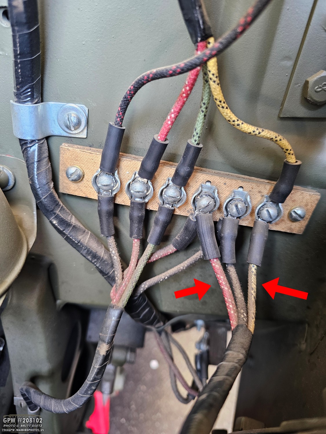
Since the headlight and marker light wires are attached to the fender, we’re going to remove these three wires from the firewall junction.
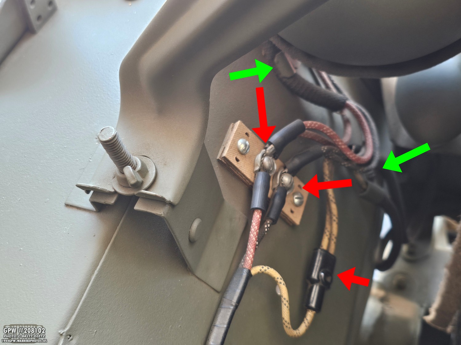
Next, you need to remove the actual headlight and marker light connectors that connect on the fender. Remove all connectors here from the junctions (red arrows) and remove the clips holding the electrical wires down (green arrows).
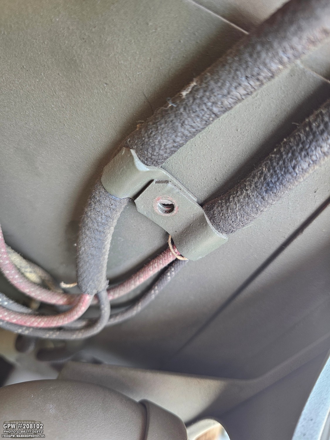
Remember how those headlight and marker light clips are put together. If they are the correct style 2-part clips, as shown here, this is what you should see when you remove the screw and nut.
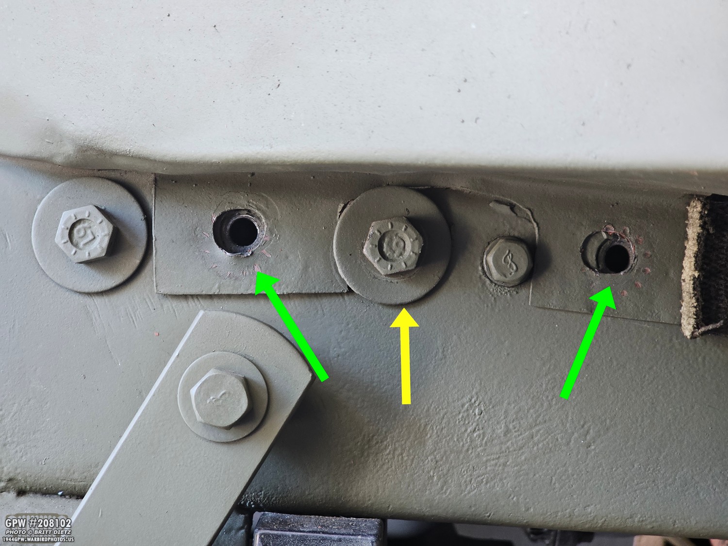
To remove the fender, remove the two bolts that hold the fender tabs to the frame (underneath the rear of the fender). If you have large washers for the steering box, then make sure you loosen those up so the tabs can come out. While I’m here, I’ll replace those two modern-style bolts. I think they are the very last two modern ones that I’d never gotten around to replacing with correct-style ones.
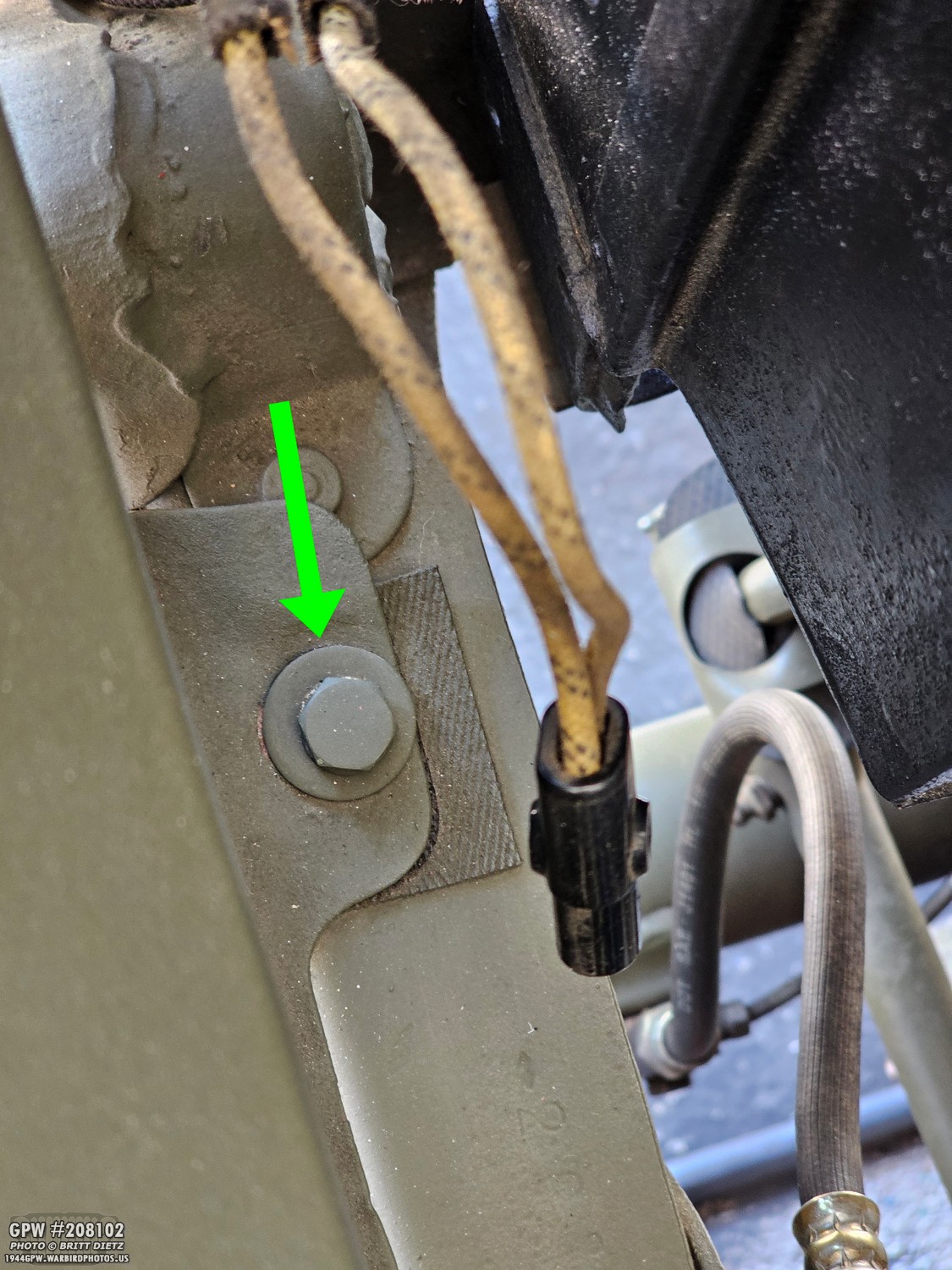
Don’t forget the bolt on the top of the frame just rear of the frame shock bracket. NOT PICTURED, don’t forget to remove the three bolts holding the fender to the body cowl, and the two bolts holding the fender to the body step. After this, you can remove the fender!
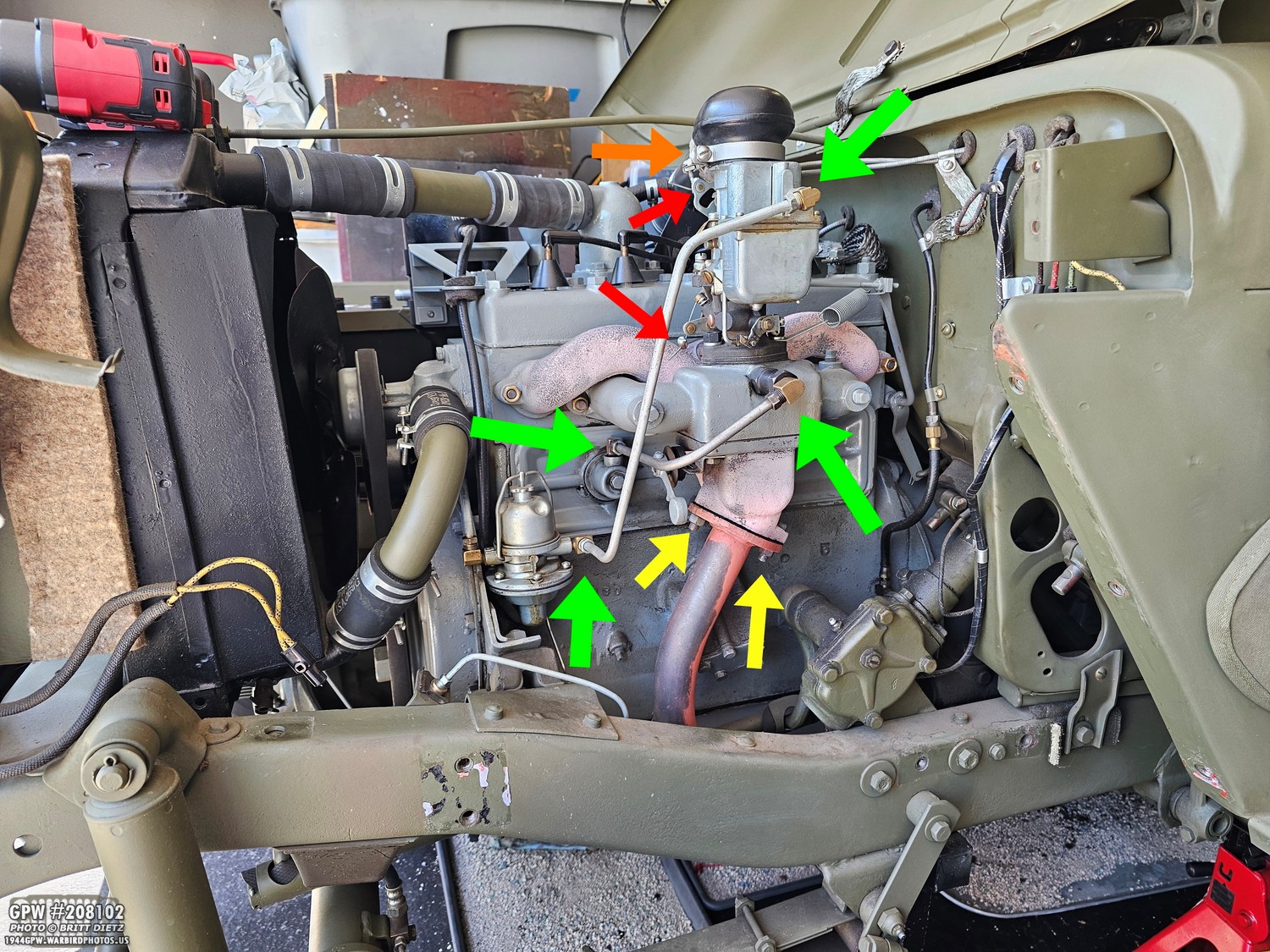
With the fender off, we can really see what needs to be removed next. The entire carburetor, manifold, and exhaust will need to be either removed or disconnected. Remove the carb air horn clamp screw (orange arrow) to separate the air horn from the carb. Remove the throttle and choke wires from the carb so they are not connected (red arrows). Remove the fuel pump to carb and valve door to PSV valve fuel lines (green arrows). And finally, remove the exhaust tube from the bottom of the exhaust manifold. You can just lay the exhaust tube down to rest against the fuel pump.
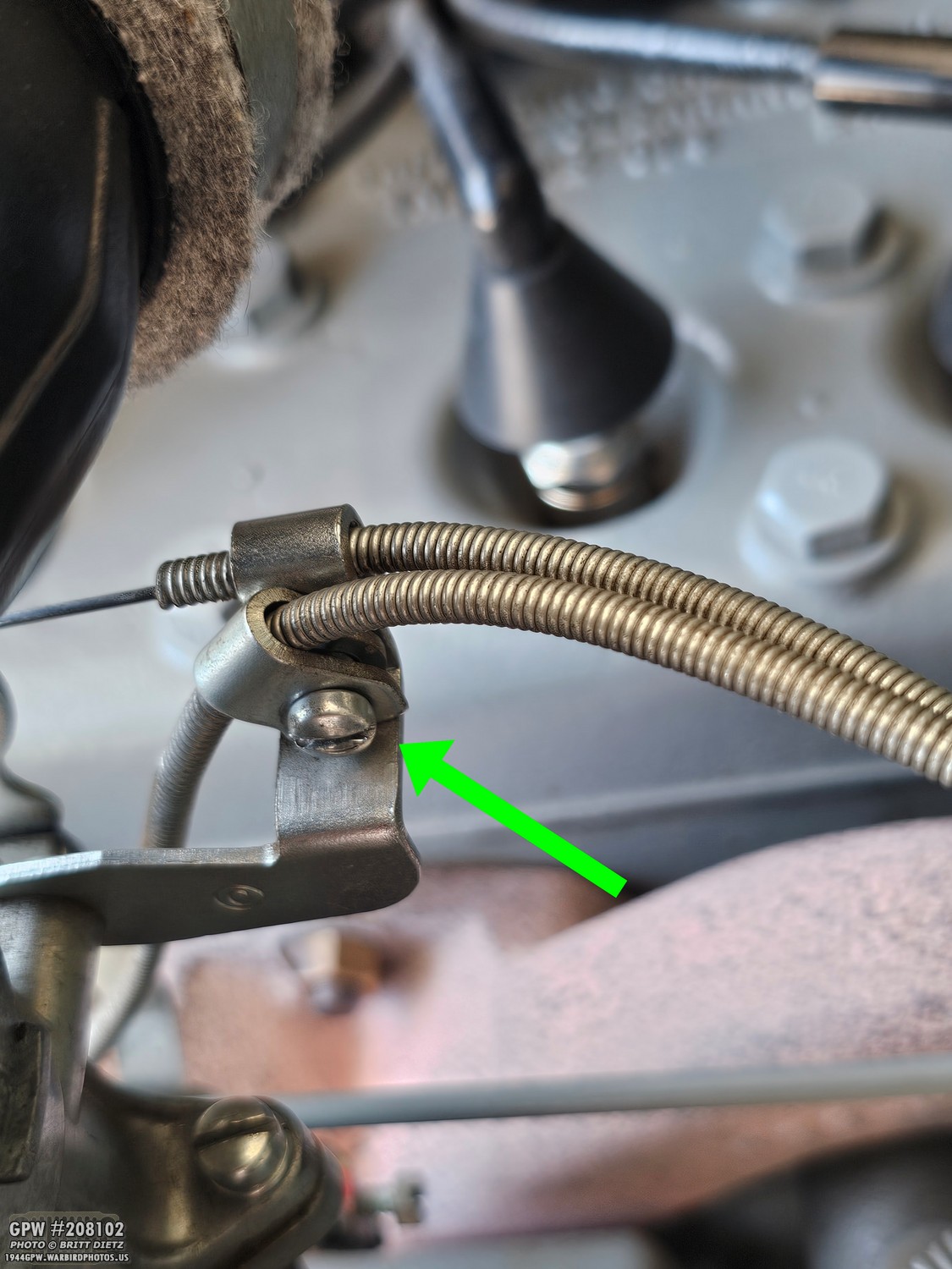
To remove the throttle wire completely from the carburetor, you need to remove the screw that holds the clamp that secures the throttle wire/sleeve.

Remove the carburetor-to-accelerator linkage spring. Also remove the cotter pin that holds the Accelerator linkage to the Accelerator linkage throttle rod to disconnect those.
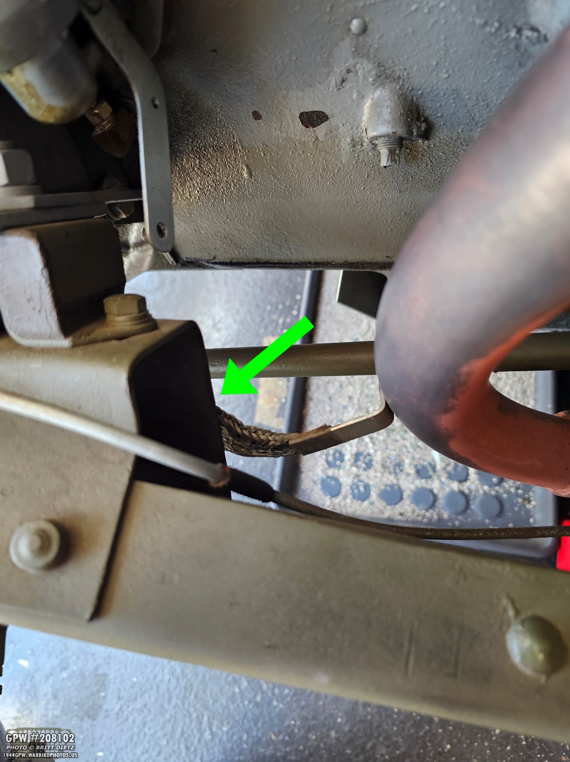
I have my exhaust tube with a ground strap welded to it (as it was for type II Radio Suppression), so for me, I had to also undo the bond strap connection on the frame (the engine mount part) in order to lay down the exhaust tube completely to get it out of the way.
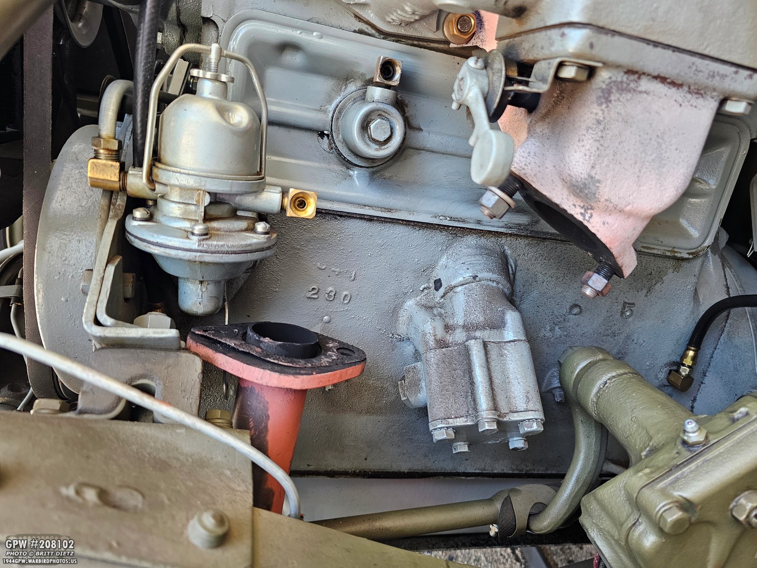
This is what it looks like with the exhaust tube disconnected and laid out of the way. I’ll put a new gasket on there as this one looked very burned up.
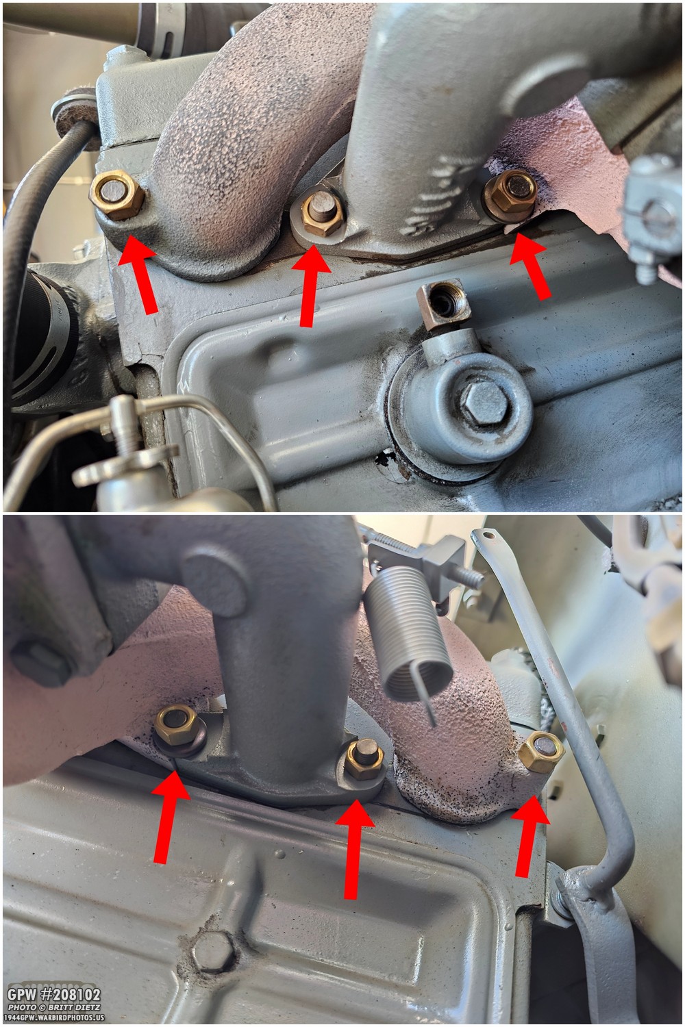
Okay, the last thing is to remove the intake and exhaust manifolds. I decided to remove them all together with the carburetor as a unit rather than individually. That means all I needed to do was remove the six brass nuts that hold the manifolds to the block. Then the entire assembly could be slid off and put aside.
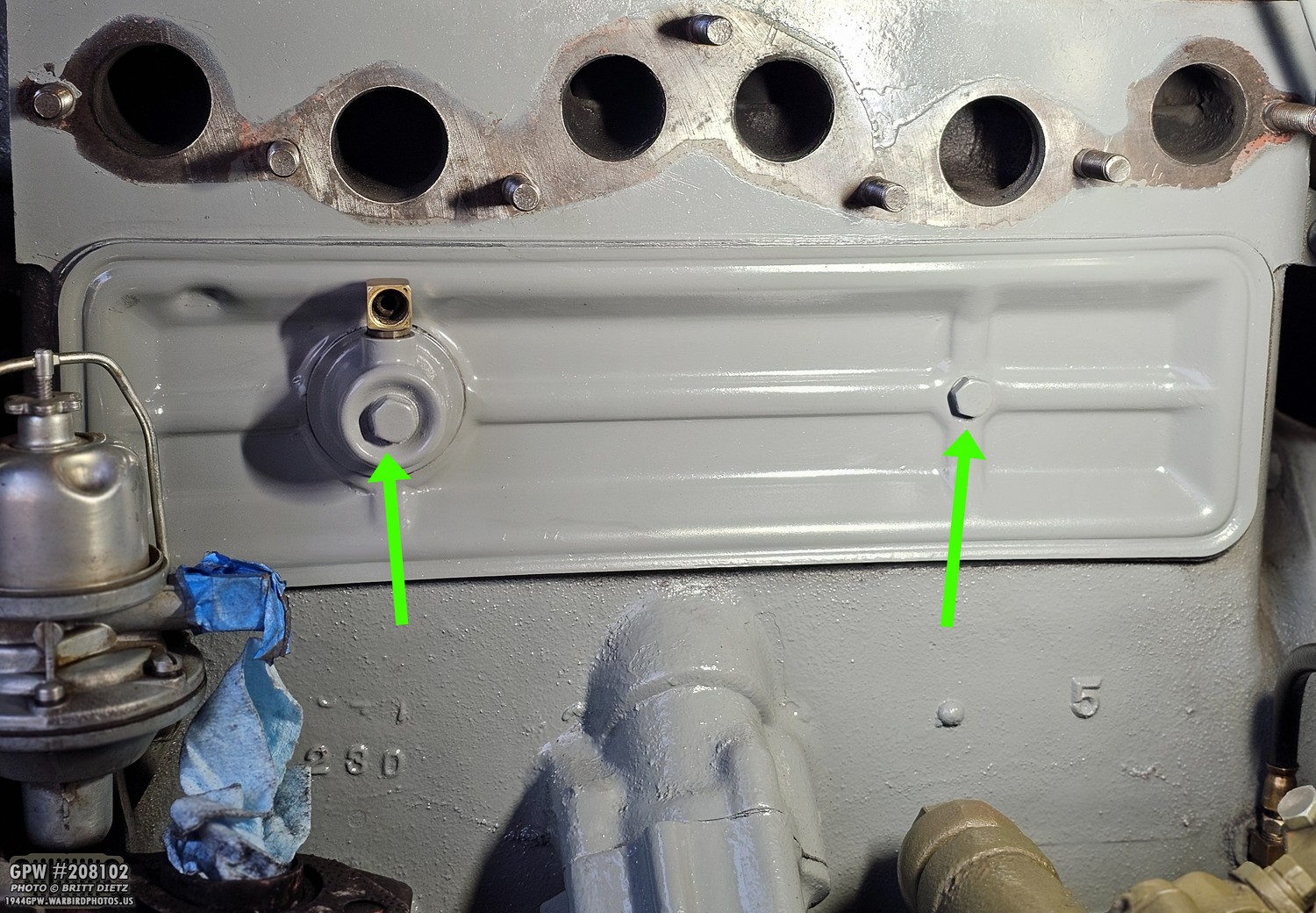
With the manifolds/carb removed, I could now access the valve cover door. There are two long screws to remove. I also taped up the fuel pump output connector and put a shop rag in the exhaust tube to keep things out.
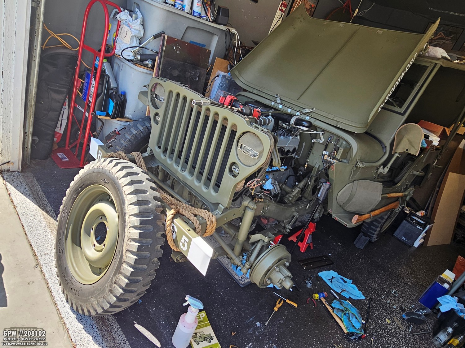
And there we go! All the prep work has ended. It’s time to get the tools and lights, and get ready for the hard part.

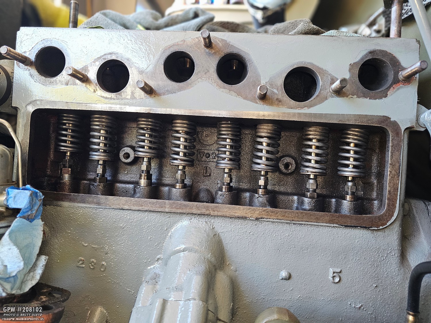
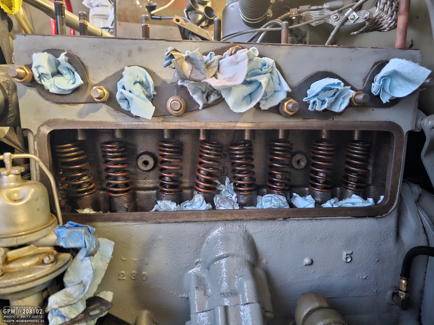
With the valve cover door open, we can now see the valves. And you’ll also see all these holes (large and small) under the valves. This is where the oil will splash up and into the valve area. Do yourself a massive favor: take shop rags and carefully place them over all the holes, completely covering the bottom area like shown here. You are going to thank me later, as you will be working with small parts that WILL fall through those holes and into the oil pan if you do not cover the holes.

Okay, let’s get started! All things are on track so far and going well. Now comes the time when you will NEED that valve compressor tool. They are about $25 on eBay for a vintage one. It’s worth having just in case you ever need to do this. As you can see in this photo, there are two sides to the end of the compressor tool. A larger cupped side at the top, and two tongues on the bottom. The tongues will rest against the flange around the adjuster screw. The larger half cups on the top will hold the bottom of the spring.
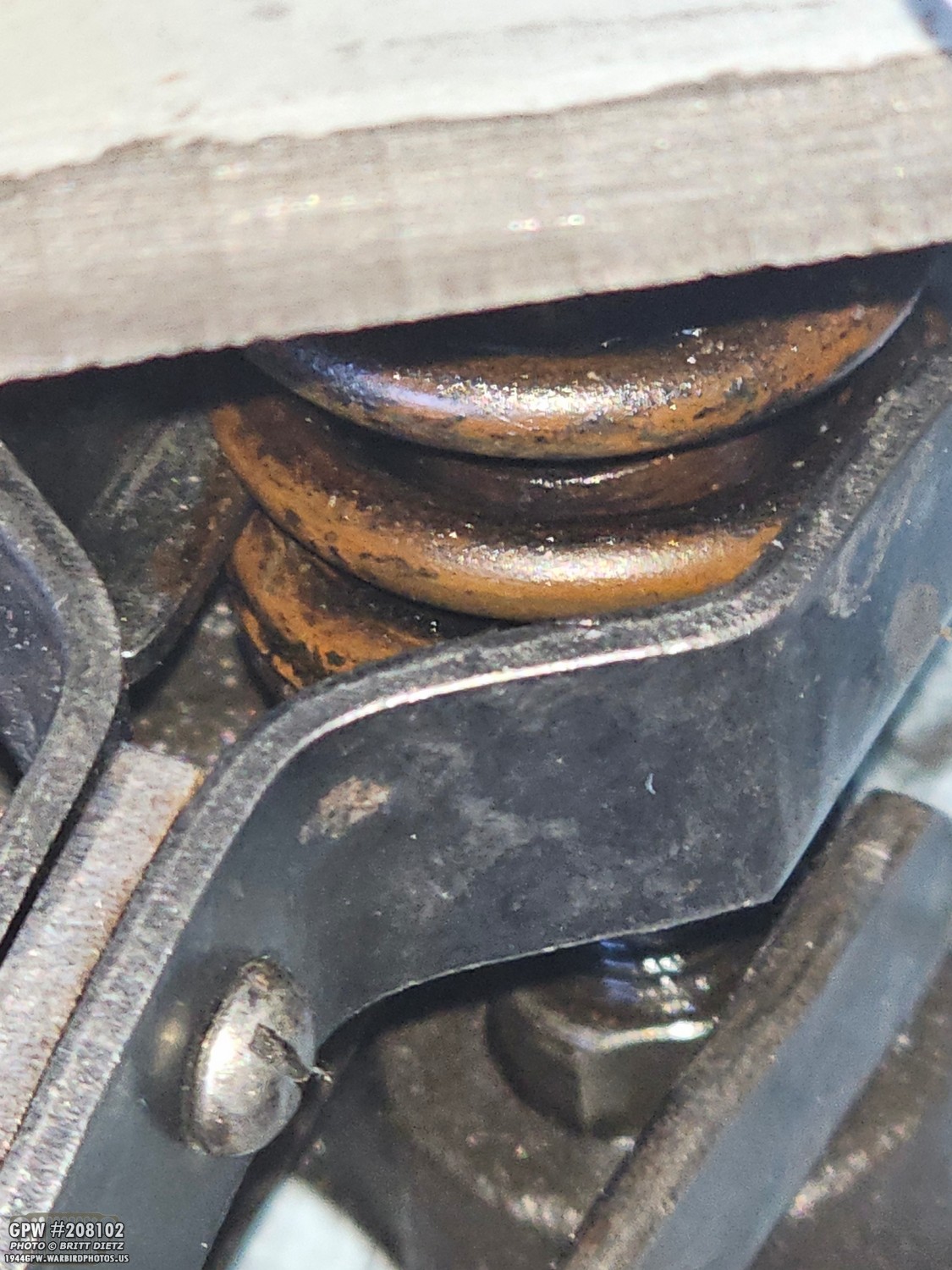
You can either try to get under the very bottom of the spring, or between the bottom and the second ring of the spring with the cups.

Once you have it in, start to turn the large + spaced knob at the other end, and this will start to expand the tool. It will then lift up the spring, compressing it to the top of the block. It should release the valve, but if it doesn’t, tap the lip of this hat-shaped valve spring retainer cap at the bottom of the valve, and the valve should fall back down, as shown, to where you can access that little hat-shaped cap (green arrow).
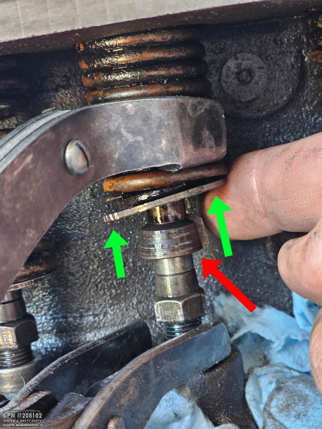
Underneath that cap are two half-moon retainers. If you take your finger and push up on the cap, it should pop up, and you’ll see the two valve spring retainer half moons that are hugging the valve stem. These little half moons are the tiny parts that, if you don’t have those rags in the oil holes, will easily pop off the valve stem and fall through those holes down into the oil pan.
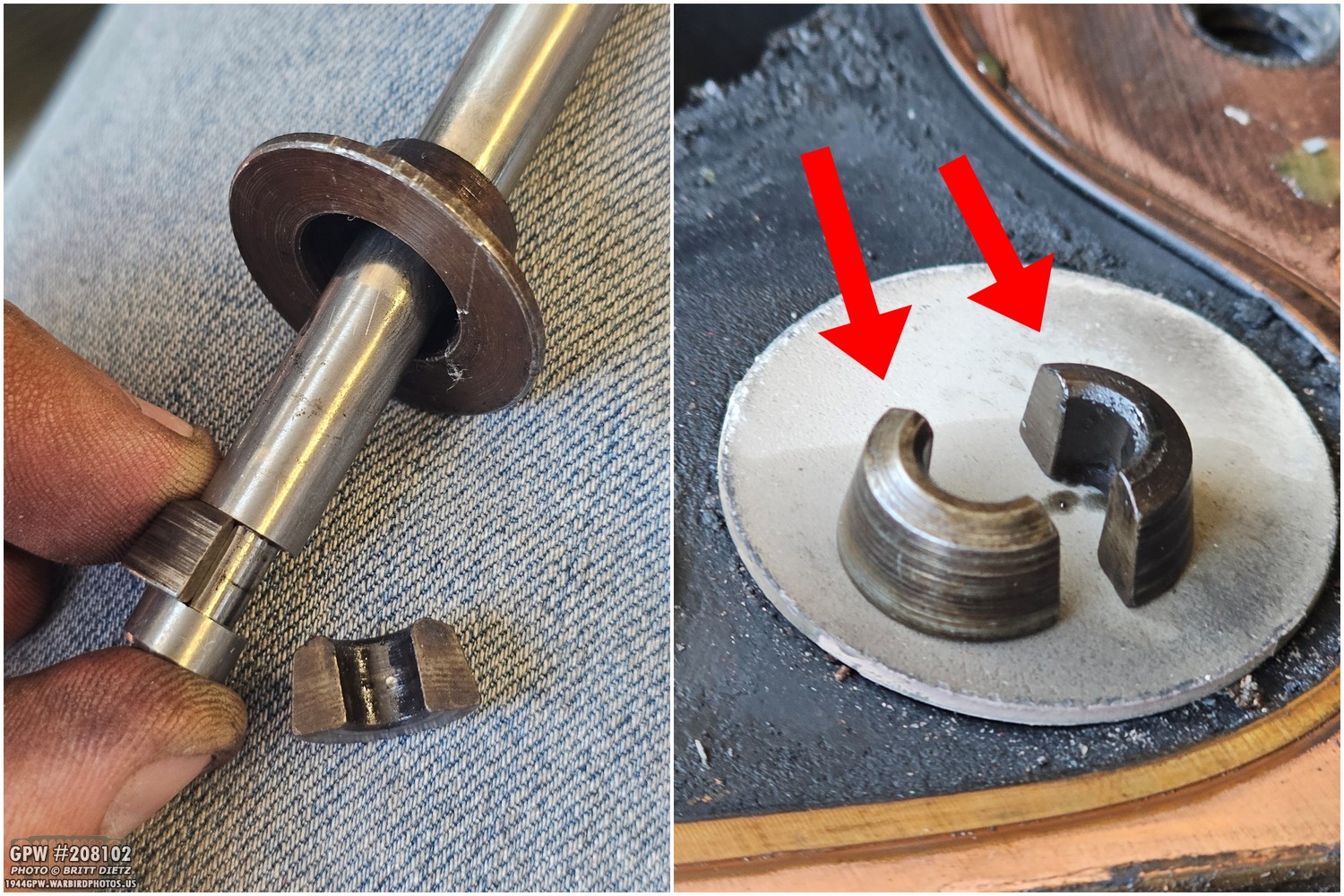
Here’s a look at those tiny little half-moon valve spring retainers. In the left photo, you can see a removed valve with the grooved area on the stem where those half-moons lock in. Together, the two half-moons form a complete donut that sits snugly right inside that groove. The hat-shaped retainer cap slides down over the stem and locks right over those half-moons, holding them in place. From there, the heavy valve spring pushes up against that cap, which keeps everything locked together and puts continuous tension on the valve so it stays tightly closed by default. Still with me?
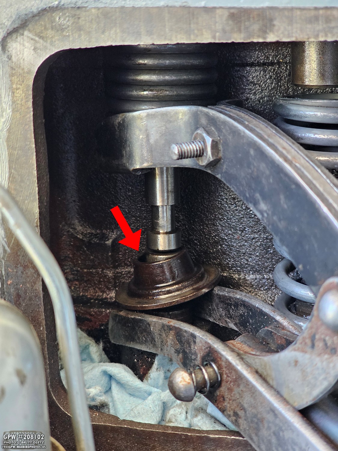
With those half moons removed, the hat-shaped cap will just fall onto the adjuster screw, so you can manually push up the valve with your finger and remove the cap.

With the cap removed, we can start to see the condition of the top of the adjuster screws. And you can already see the top of the screw has a lipped wall around the edge, which means these are heavily cupped and worn. Not only do these adjuster screws push the valve up (against the tension pressure of the spring), but they also rotate the valve in the process so that when the valve closes, it’s not closing in the same rotational spot as before. This helps with wear and buildup that can cause the valve to not seat correctly when closed over time. But the downside is that it can wear the tops of the adjuster screws over time from that up, down, and rotational movement with the valve.
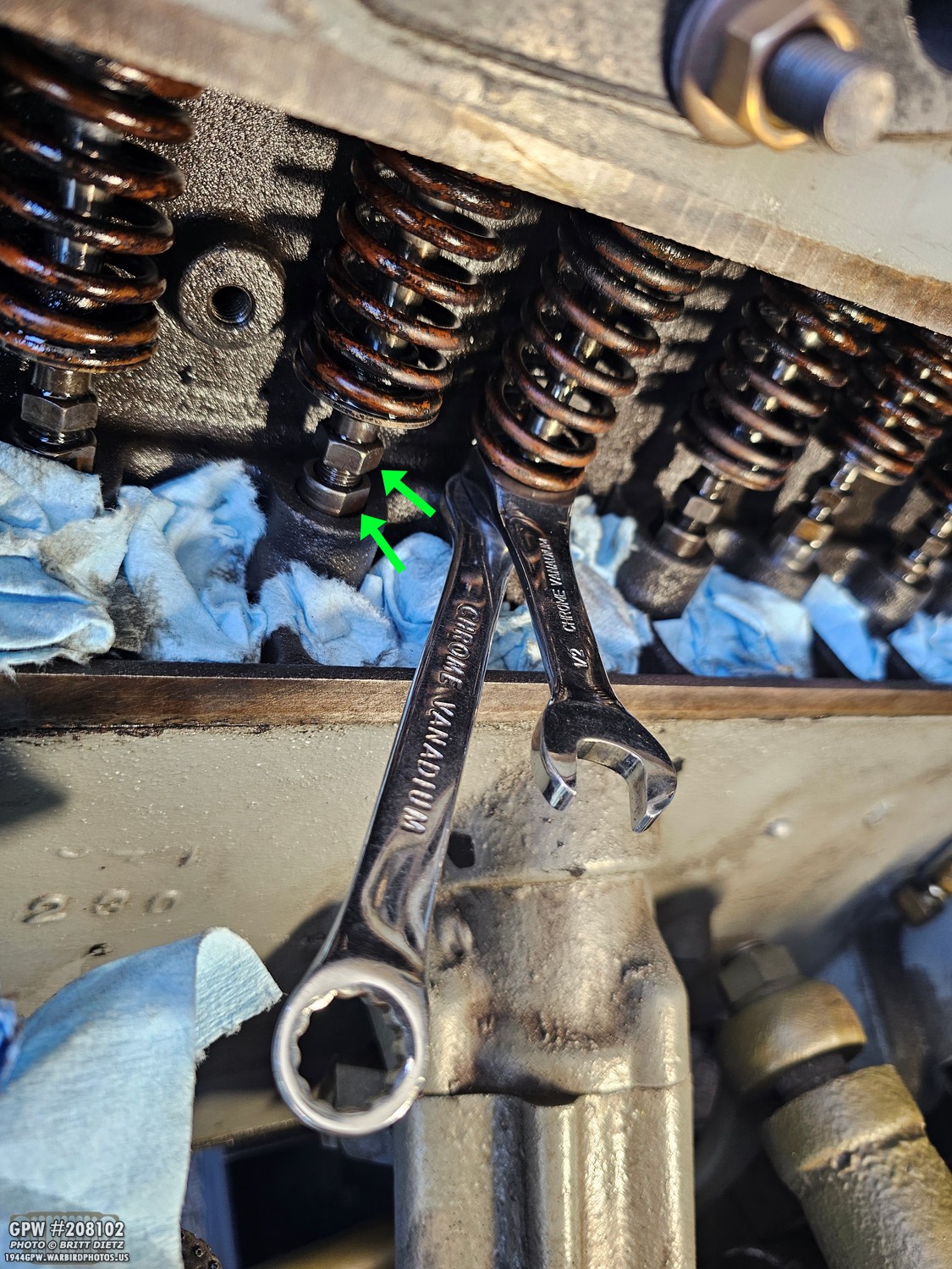
Now it’s time to remove the adjuster screws. You need two wrenches. They could be a combination of 1/2 and 7/16, or both 1/2s. Depends on the size of the adjuster screws. Some earlier adjuster screws were smaller and needed 7/16; the later ones needed 1/2. If you were to try and just unscrew the adjuster screws, you’d fine all you’d be doing is spinning the tappet with the screw. You have to hold the tappet from spinning under the adjuster screw with one wrench, and then unscrew the adjuster screw with a second wrench. On the photo, the arrows show the two spots where the wrenches go. The bottom arrow is the tappet that needs to be held in place, and the top arrow is the adjuster screw that needs to turn counter-clockwise to unscrew. This is also how you adjust the adjuster screw to have more or less gap when adjusting the valves. But more on that later.
Unscrewing the adjuster screws isn’t easy. It’s a long, time-consuming process as there are two sets of threads on the adjuster screws. As you unscrew it, it should lift the valve up since the springs are no longer tensioned.
Unscrewing the adjuster screws isn’t easy. It’s a long, time-consuming process as there are two sets of threads on the adjuster screws. As you unscrew it, it should lift the valve up since the springs are no longer tensioned.
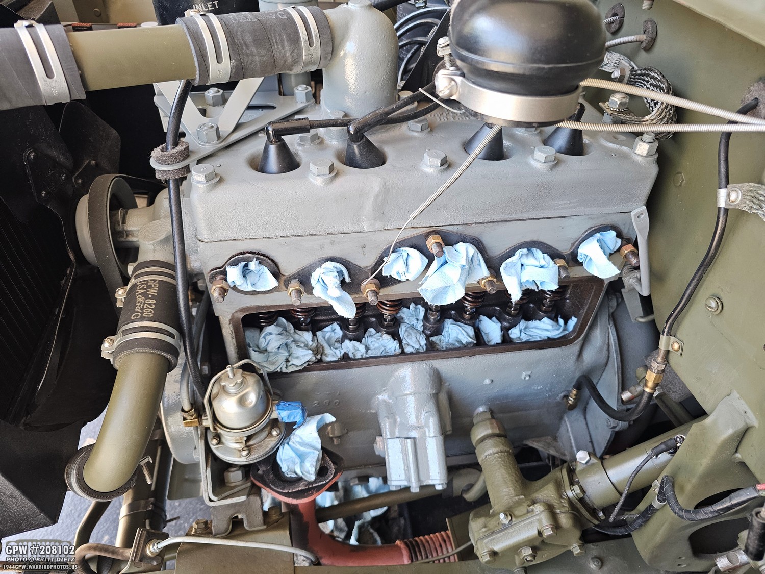
And this is where everything fell apart for me. I thought I’d be able to remove the adjuster screws, install the new ones, adjust them, and be on my way to putting things back together. Well, after unscrewing the first adjuster screw, I found out that this project was about to take much longer.
Basically, the valves can only lift so much before they will hit the top head of the block. After that, they won’t move anymore. Smaller adjuster screws, like the earlier ones, can be removed with little to no space left for the valve to go up, but enough that you can get the screws out with some effort. Well, turns out I have later-style adjuster screws. I had no more give from the valve to go up and still about 2 threads left on the screw. UGH!!!!
What does that mean? The head has to come off so you can raise the valves higher. That means draining the coolant, disconnecting the oil line, removing the oil bracket, disconnecting the coolant tubes, removing the spark plugs and wires, etc. That also means having to order a new head gasket, torquing all the bolts again, and more. Sigh. I seriously considered just saying ‘Nope, not worth it!’ and living with the tapping noise… but as I sat there pondering life, I decided, well… I’ve changed the head gasket twice already. Let’s just do this.
Basically, the valves can only lift so much before they will hit the top head of the block. After that, they won’t move anymore. Smaller adjuster screws, like the earlier ones, can be removed with little to no space left for the valve to go up, but enough that you can get the screws out with some effort. Well, turns out I have later-style adjuster screws. I had no more give from the valve to go up and still about 2 threads left on the screw. UGH!!!!
What does that mean? The head has to come off so you can raise the valves higher. That means draining the coolant, disconnecting the oil line, removing the oil bracket, disconnecting the coolant tubes, removing the spark plugs and wires, etc. That also means having to order a new head gasket, torquing all the bolts again, and more. Sigh. I seriously considered just saying ‘Nope, not worth it!’ and living with the tapping noise… but as I sat there pondering life, I decided, well… I’ve changed the head gasket twice already. Let’s just do this.

So, I got to work… first things first, drain the radiator and most of the coolant out of the Jeep. It just needs to get low enough that I can remove the top thermostat-to-radiator tube and also remove the head. I’ll still wait for the majority of the coolant to drain, as it’s been a while since I did a coolant change anyway.
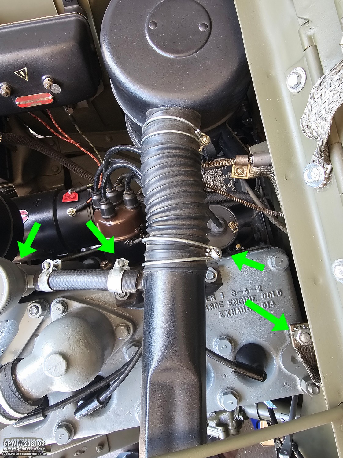
Now to remove the various connections. The bond strap on the rear of the engine, the air cleaner to crossover tube clamp, and the dipstick tube air vent tube.

Next, the oil line that goes to the oil filter, the bolt holding the dipstick tube tower to the oil filter bracket, and then the four clamps for the thermostat to radiator tube. Don’t forget the radiator hold-down bar (blue arrow).
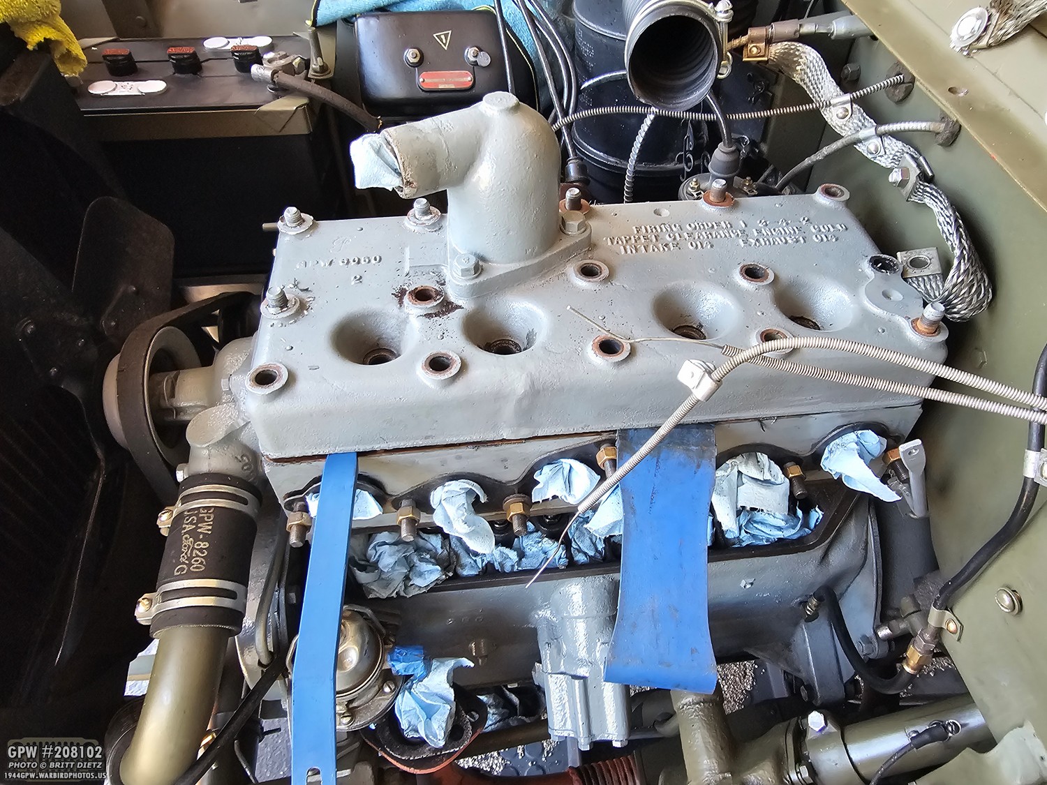
With all that removed, I could unscrew all the bolts/nuts from the head. The head was on there nice and tight, so I used plastic upholstery wedges to slowly break the head gasket seal.
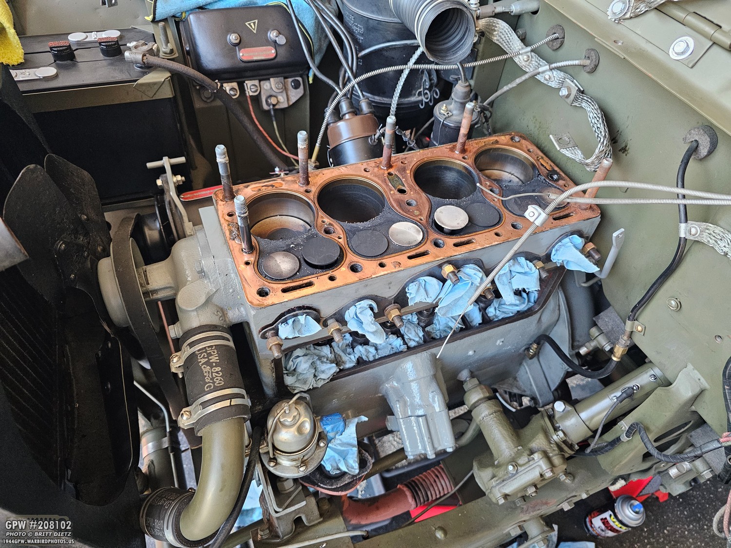
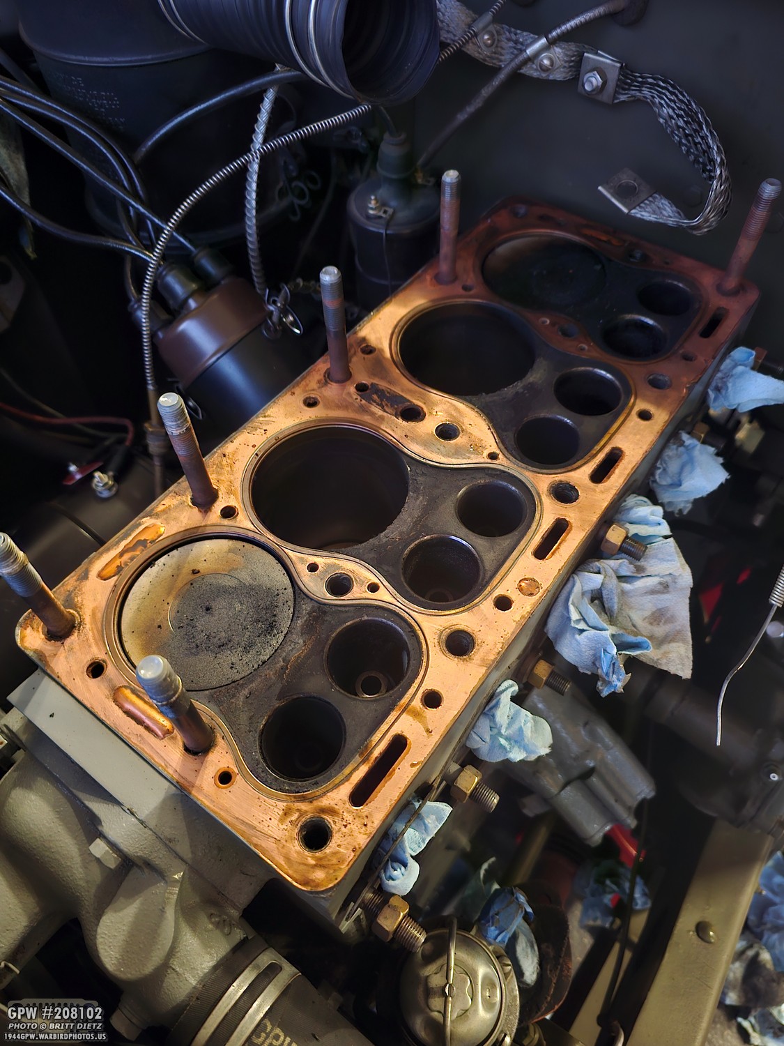
A bit of a mess, but finally the head is off! The gasket decided to stay with the block rather than the head due to the RTV sealer. As you can see with the heads off, all eight valves are no longer constrained by the head and can be lifted all the way up.
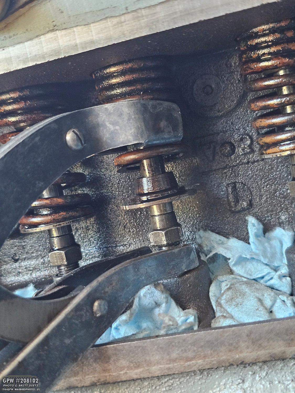
So, back to the side valve area to do what we started. I compressed the spring again and got to work removing all the retainer caps and half-moon retainers from the rest of the valves.

As you can see here (sorry for the not-sharp shot, was shooting one-handed), you can push the valves all the way up/out.
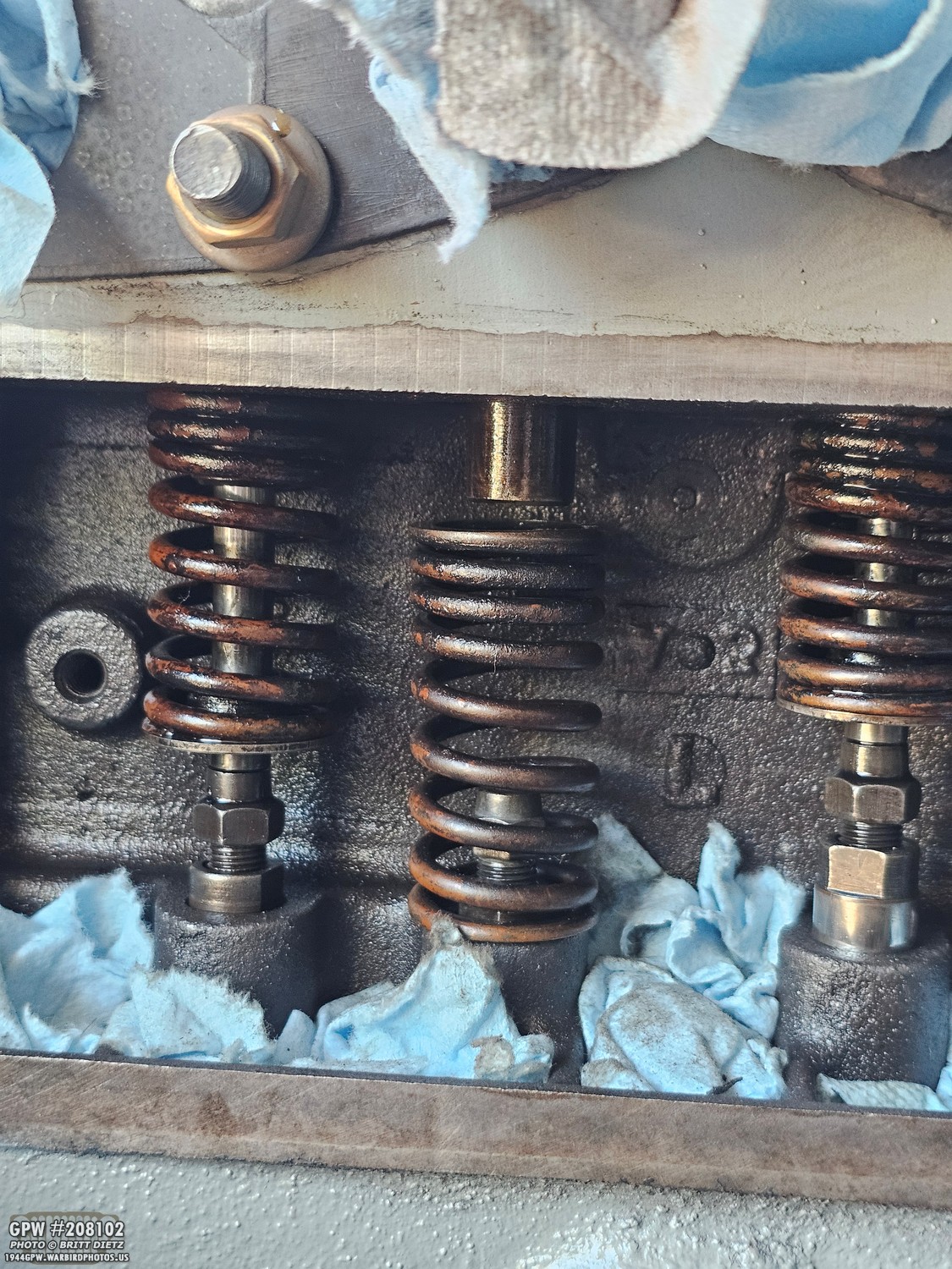
I found it was just easier to remove the entire valve. BUT, make SURE you mark/keep track of which valve went to which spot. This is IMPORTANT. I put the valves, the hat-shaped caps, and the half-moon retainers all in individual bags for each valve and numbered them 1-8 so I knew right where they went.
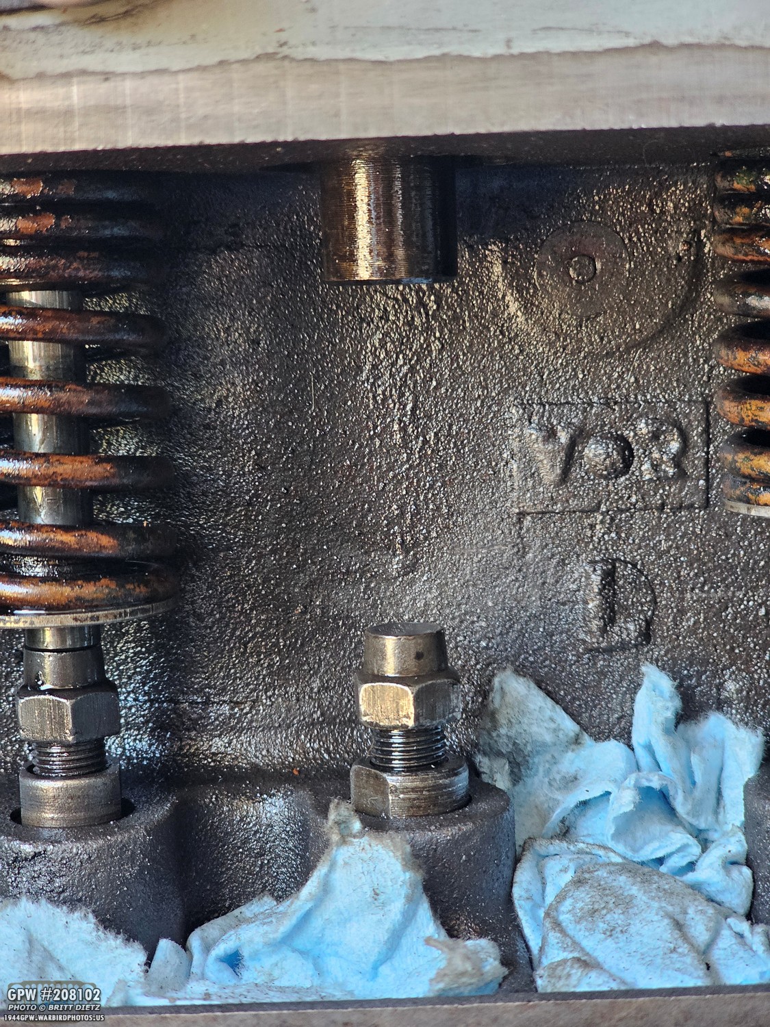
With the valve removed, we can also remove the springs. This makes life so much easier getting the adjuster screw out, which you can easily see now, and the tappet that it’s screwed into.
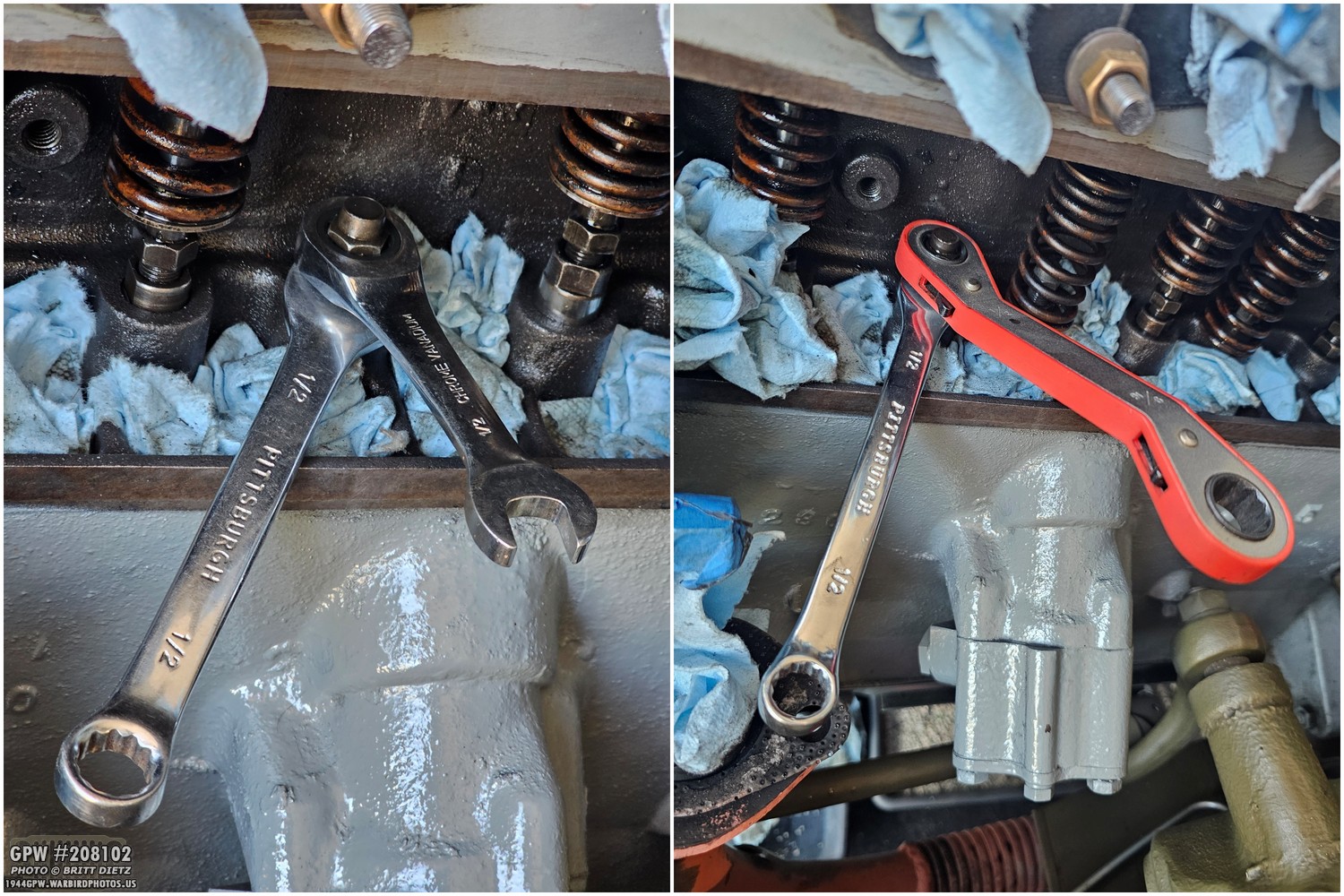
With all this extra space, you can switch to your favorite ratcheting wrench, which I started with a stubby one but then changed to this large one. This made unscrewing the adjuster screw so much easier. They are in there tight, so having it helps make the process much faster.

And now we have the first adjuster screw out. We can compare it to the NOS original ones I got. Looking at the top of each one in the left photo, you can see just how cupped the screw is. Also interesting to note is that the NOS originals I got were slightly smaller (height-wise), which suggests these might be earlier war-style adjuster screws. Both work in the standard L134 engine, so it doesn’t matter which one you use.
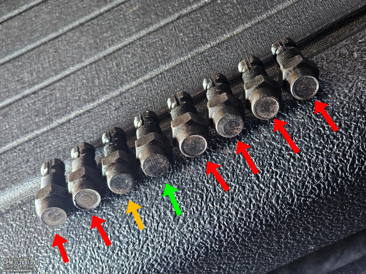
After a bit of work, I got all eight of the worn originals out. Of them, only one of them was not cupped. Some were HEAVILY cupped; others moderately cupped. One was only slightly cupped. But I’ll replace them all.
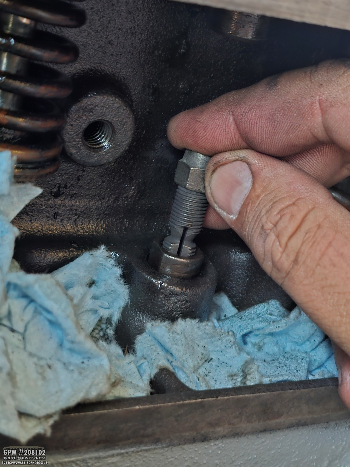
To replace them, just reverse the process. Start to screw one of the new adjuster screws in by hand. That won’t last long, as you’ll find that it gets tight really fast and you’ll need to switch to the wrenches.

Unbeknownst to me was the second delay, as I was already waiting for a new head gasket to arrive. As I was compressing the springs, I realized that I should probably check the springs while they were out. Something I hadn’t done.
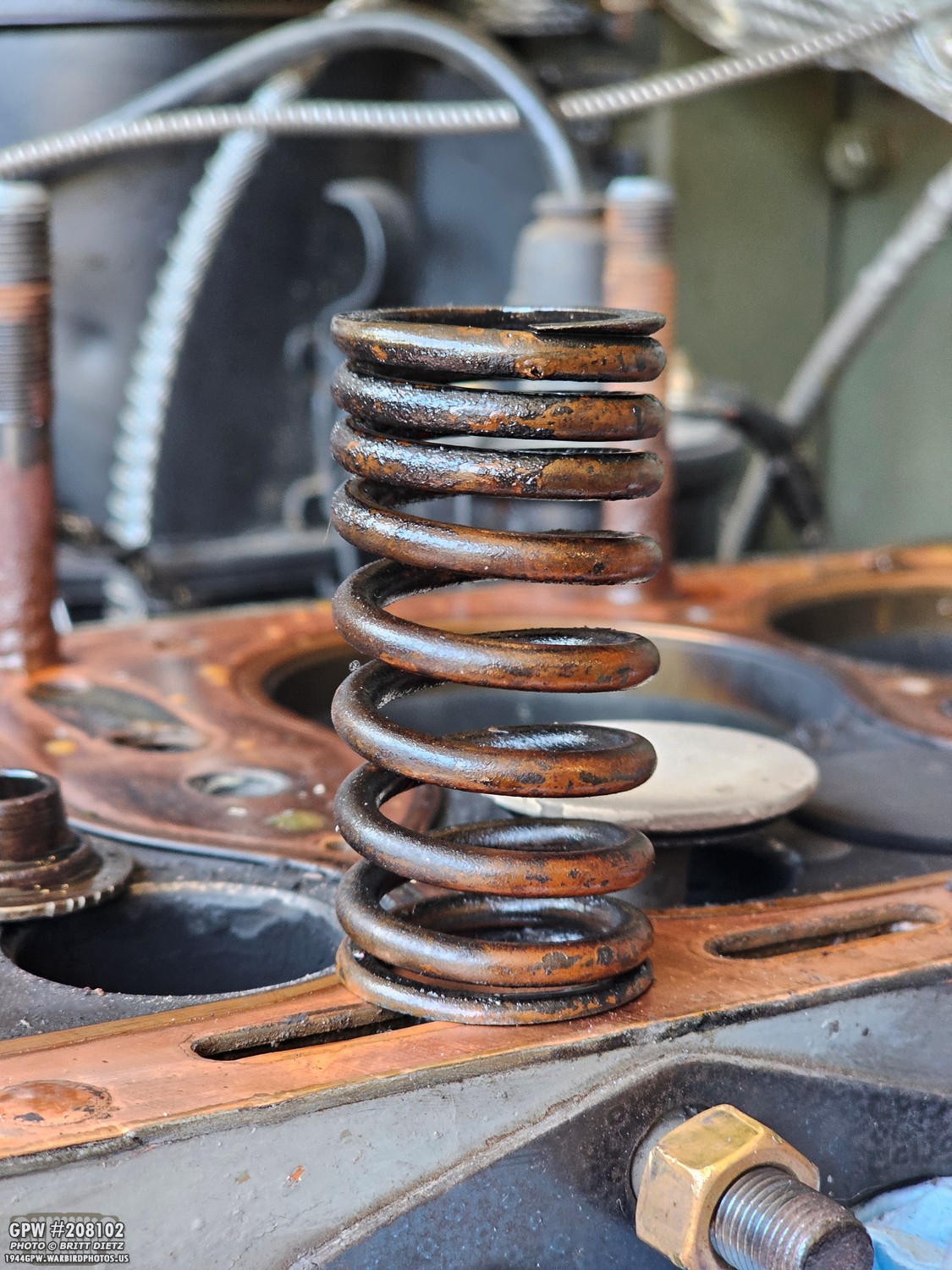
With the springs out, I could measure how tall they were when not compressed. According to the TM 9-1803A Technical Manual (page 37), it says, “Measure the free length of each valve spring; if less than 2.5 inches in length, the spring must be replaced.” Well, mine were between 2.18 and 2.24 inches. Ugh. So, that means a second order, waiting for new valve springs to arrive.
At this point, we were already a week and a half into this project, as I had to wait for the new head gasket to arrive (also because it takes two business days, plus I can only work on the Jeep Saturday-Mondays). What’s another week to wait for new springs?
I didn’t just not work on the Jeep, however, as I waited. I did little things that I could do. That included turning to the top of the block to remove the head gasket and clean everything up.
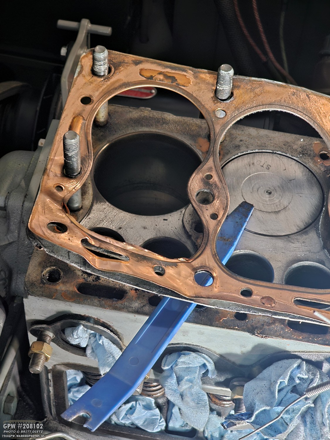
I used the same plastic upholstery wedges to pull up the head gasket, which started to split apart.

Here’s a look at the top of the block without the gasket. I’ll need to clean up the studs, remove all the leftover RTV sealer around the coolant holes, and I’ll make sure to clean up the flat mating surface.

Since the head and the side valve door were off, I decided to clean them up and refresh their Ford Engine Grey paint job.

I also touched up the paint on the side of the block where the manifolds go. I used the old manifold gasket wrapped with blue painter’s tape to block the paint from getting inside the holes or the studs.
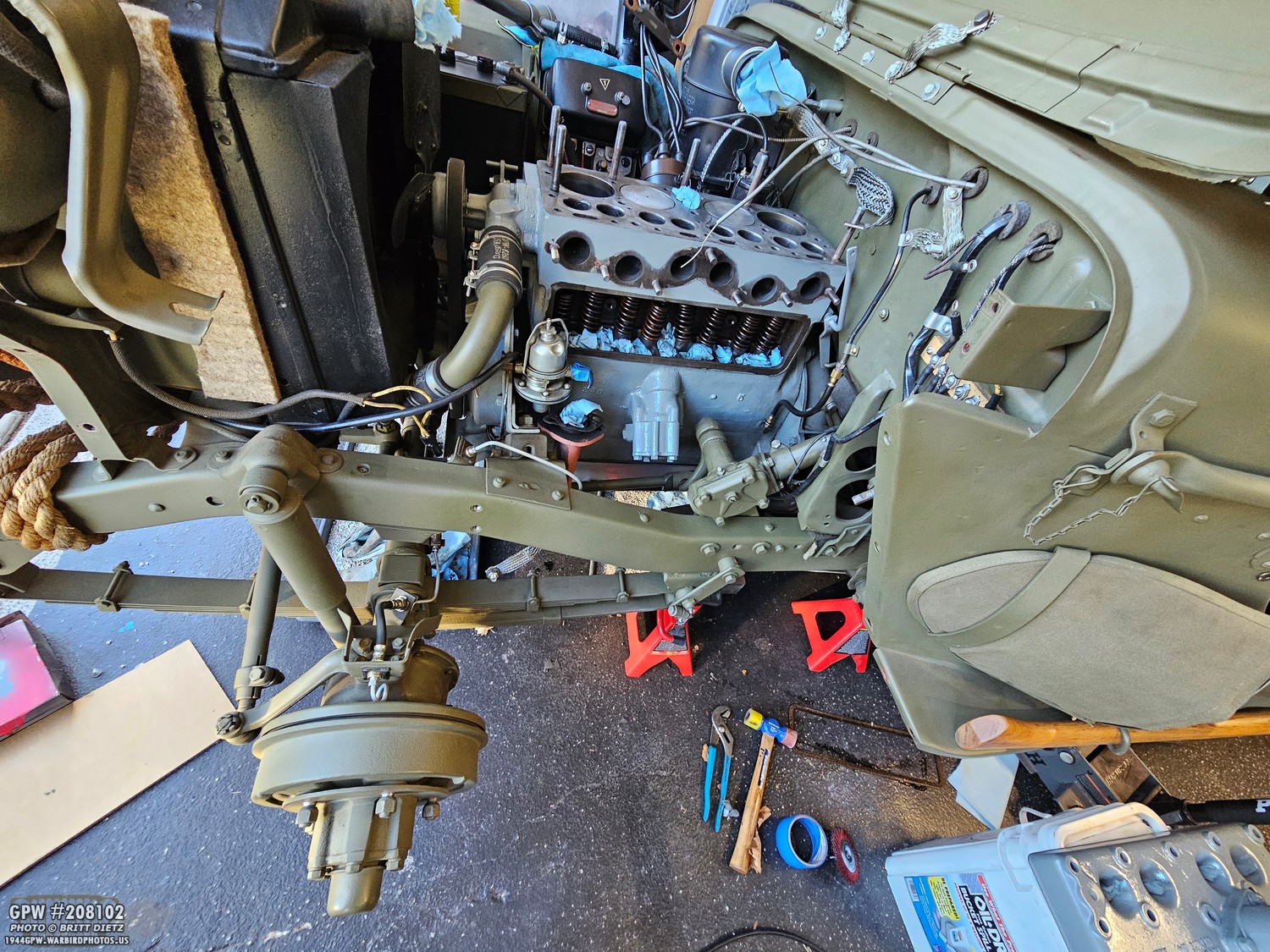
I also repainted the frame and body firewall where the fender and/or other things might have scratched the OD Green. Looking nicer already! I wanted to make sure I got as much done as I could while waiting for parts.

And here’s the first parts delivery from Ron Fitzpatrick Jeep parts. Where I live, they typically get here in 2 business days. A new head gasket (copper), new manifold gasket, new valve door vent hole gasket, new correct bolts for the steering box, and a new cork valve door gasket. The springs would be in a separate order since I ordered them later.

But let’s jump to that when they arrive. You can see the new springs ARE taller than the ones I took out (new one on the left, old one on the right).

Here are all the new springs installed. Now it was time to start putting things back together! We’re at about the 2-and-a-half-week mark now.
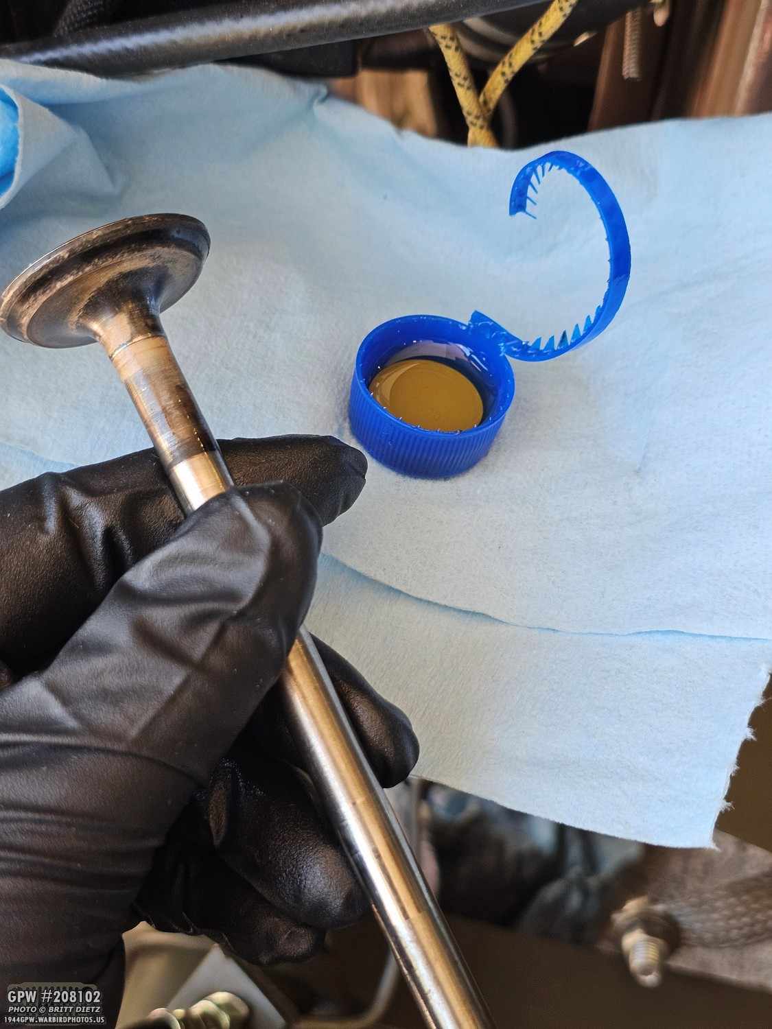
The first step is to put the valves back in (in the correct spots I took them out of). You don’t want to reinstall them dry, so I used some SAE 30 oil (same as the engine) to coat the stem when putting them back in.
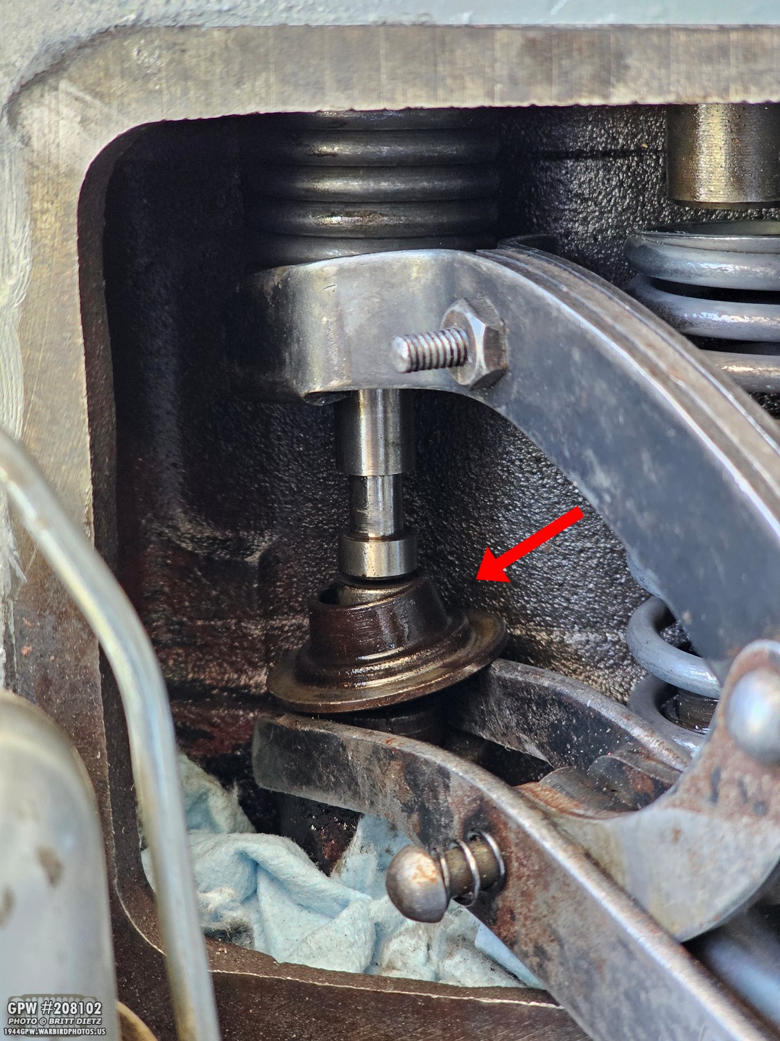
With the valves back in, I then put the hat-shaped cap back on and compressed the spring.
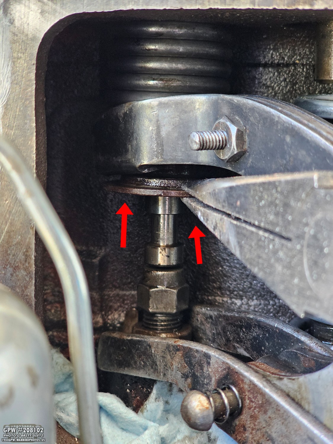
Using needle nose pliers, I lifted the cap to reveal the indented area for the half-moon retainers.

Before installing the half-moon retainers, I put a small tab of grease inside them. This is to help hold them on the valve stem while installing both of them.

Here’s the first half-moon retainer installed. Careful, they like to easily pop off. Thankfully, we have those blue shop towels there still to catch them!
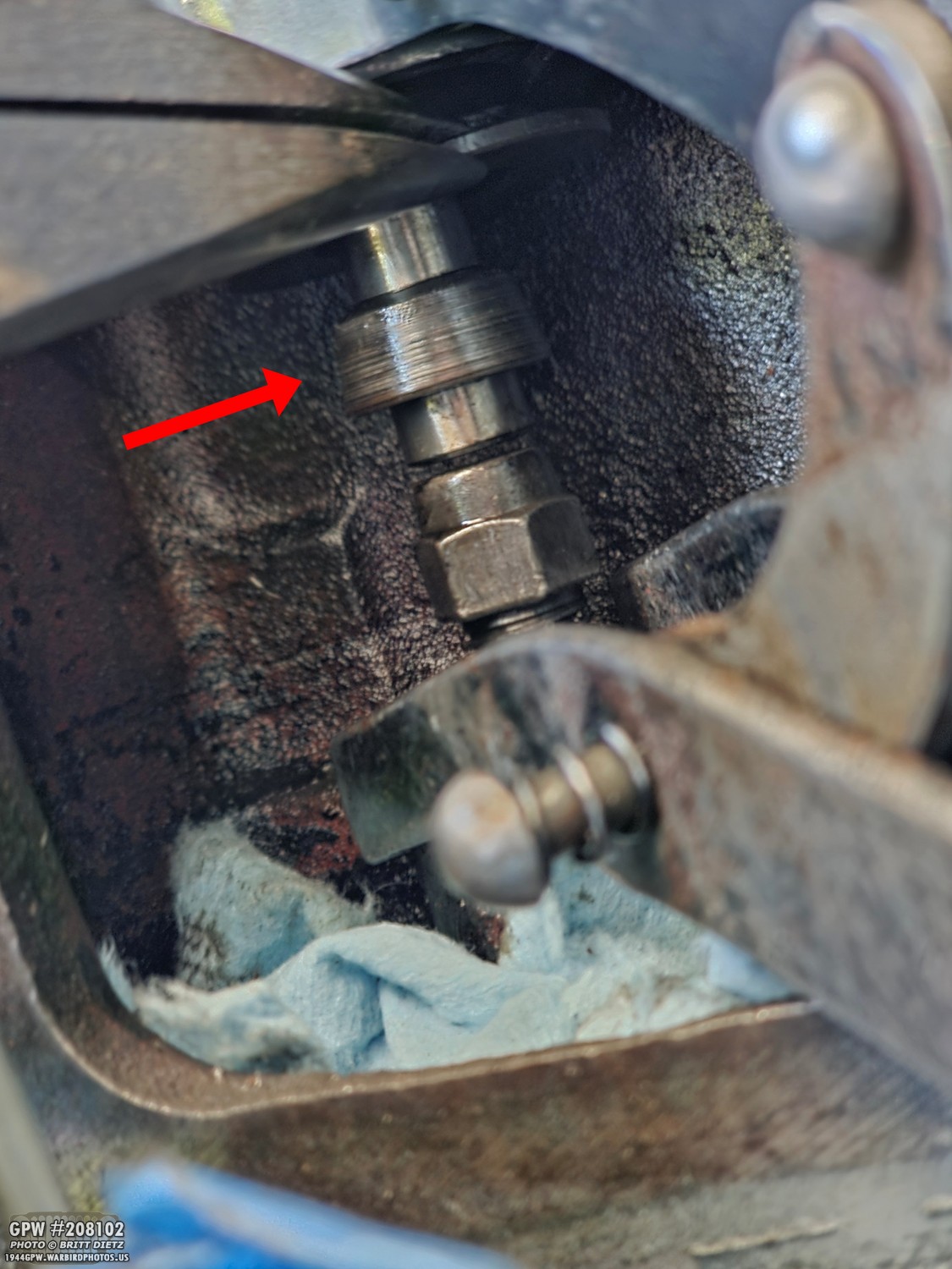
And here’s the other half of the half-moon retainers installed. I found it best to hold a finger on the first on so it doesn’t pop off as I, with the same hand (because the other one is holding the cap up with the pliers), pushed the other half-moon retainer on. Once both are on, they seem to hold pretty well (especially with the little dab of grease).
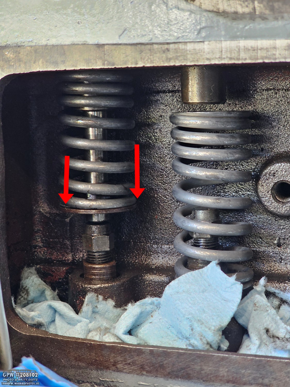
From there, you can unscrew the valve compressor tool, which will push down on the hat-shaped cap as it expands, and then lock those half-moon retainers in there. The cap will stop when over the retainers, and you’re done reinstalling things for that valve; move on to the next one.

Here’s all of the valves/caps/retainers installed. All that’s left to do with them is the adjuster screw lash (gap) on them.
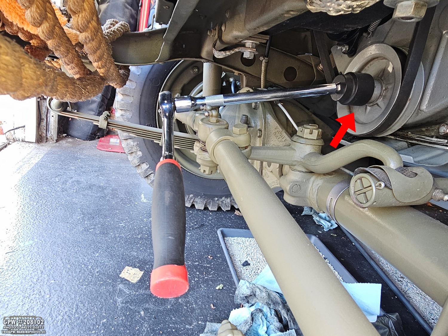
So, let’s get to adjusting the valves and that lash! You’re going to need a way to turn the engine manually. You can use the manual hand crank, but I found getting a socket to fit over the crankshaft nut on the front pulley with a large ratchet will allow you to stay on the valve side of the engine and turn it without having to go in the front of the Jeep each time. Plus, now I can watch the valves as I turn the engine, because that is very important for the next steps.
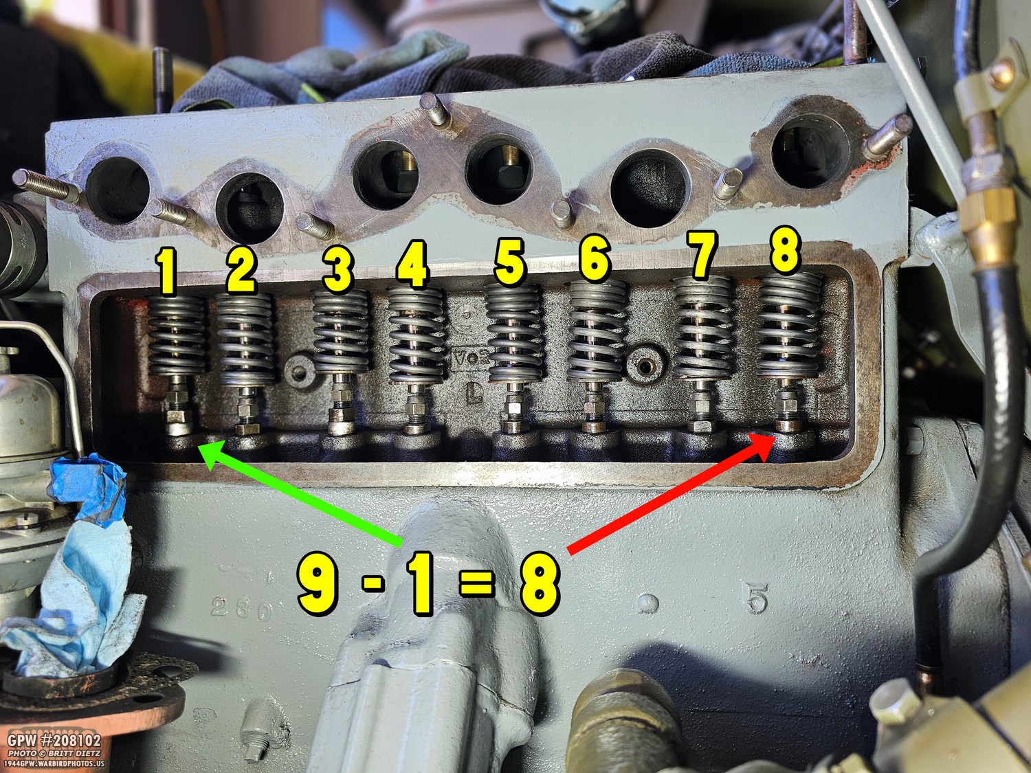
To adjust the valves (which is adjusting the adjuster screws… not doing anything to the valves themselves), we’re going to use the rule of 9s. So, let’s assign a number to each of the valves starting with 1 and ending with 8. Turn the ratchet (or hand crank) to turn the engine (turn clockwise). Watch for one of the valves to start being lifted (open). Turn the engine SLOWLY; the second the valve you’re watching stops rising, STOP. Because it will very quickly start to lower if you keep turning.
You then take the number 9 and subtract it from the number of the valve that is in that up position. So, in this photo, the #1 is at the highest (#3 is also just about the highest it can go). But #1 stopped moving up, so you take 9 – 1 (the valve number), and you get 8. That means Valve number 8 is at the lowest it can go, which is where the gap between the adjuster screw and the bottom of the valve needs to be adjusted.
You then take the number 9 and subtract it from the number of the valve that is in that up position. So, in this photo, the #1 is at the highest (#3 is also just about the highest it can go). But #1 stopped moving up, so you take 9 – 1 (the valve number), and you get 8. That means Valve number 8 is at the lowest it can go, which is where the gap between the adjuster screw and the bottom of the valve needs to be adjusted.

To adjust it, it’s as easy as taking two wrenches. You use the bottom wrench to hold the tappet in place, just like you did when you were removing the adjuster screws, and you will either turn the adjuster screw clockwise to lower it (increase the gap) or turn it counterclockwise to raise it (decrease the gap).
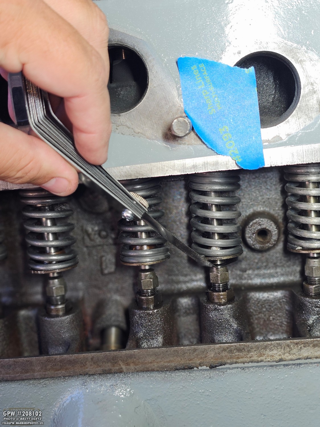
How you measure that gap is with a feeler gauge. I’m using a special valve feeler gauge here that has an L-shaped end to make it easier to insert between the valve and the adjuster screw. Now, the question becomes what gauge you should use. Originally, I was going to use .014, which is what the head of my engine says, but I was told to instead use .013 for the engine by several people. Spoiler alert: this would end up being the source of major issue #3, making me do all this over again. Turns out my engine specifically wants .014 for the clearance. But we’ll get more into that in the next update.
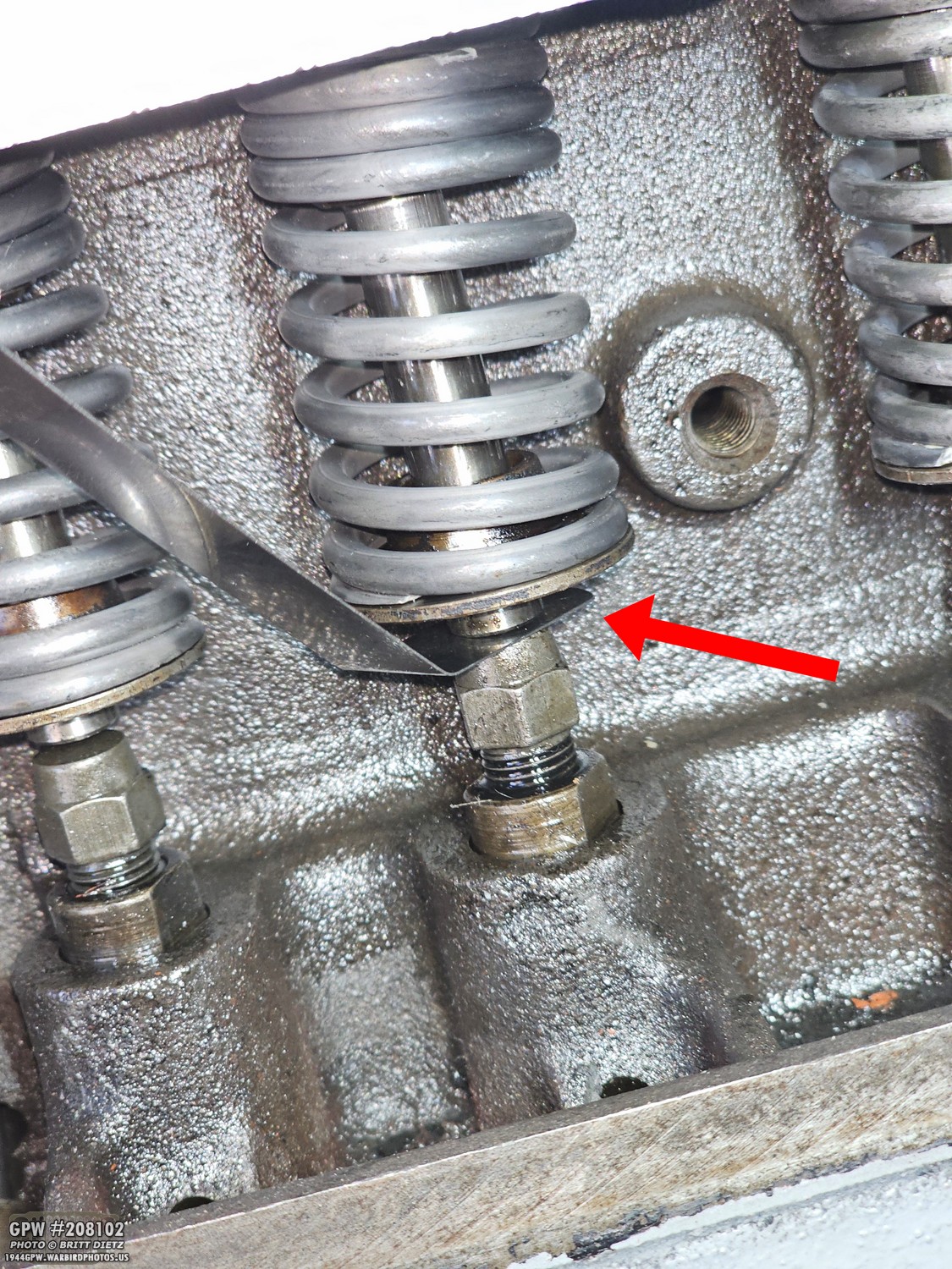
Here’s a better image showing the feeler gauge in between the valve stem and the top of the adjuster screw head. You want the feeler gauge to be insertable, not so much that it’s super easy. There should be a slight drag/resistance to push it in and pull it out of that gap. If you can slide the gauge in and out super easily, the gap is too much. If it gets stuck in there and you can’t pull it out, it’s too little. So, you go back and adjust the adjuster screw by screwing it more in (to increase gap) or screw it out (to decrease gap) until the feeler gauge has resistance, but you can pull/push it in and out.

It took a while, but finally all the valves were adjusted to .013, and the engine was ready to be rebuilt. Again, spoiler alert: if only I’d known that my engine wanted .014 gapping!
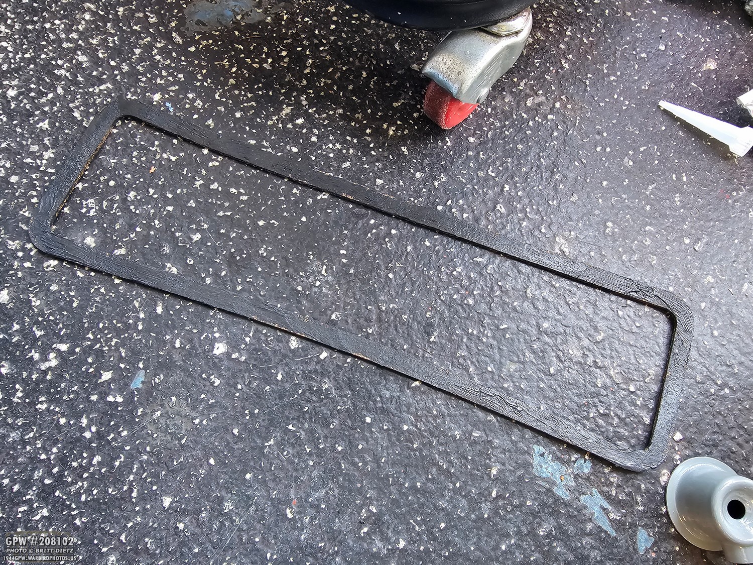
First, I coated one side of the new cork valve door gasket with black (high heat) RTV. ONLY put it on one side, and ONLY on the side that meets the block.

Door is reinstalled!
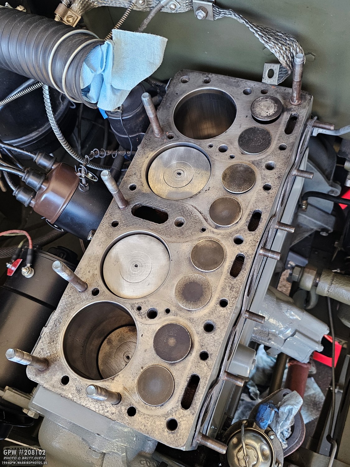
I turned my attention to the stop of the block. I got it looking nice and clean. I also retapped the studs to make sure the threads were in the best shape.
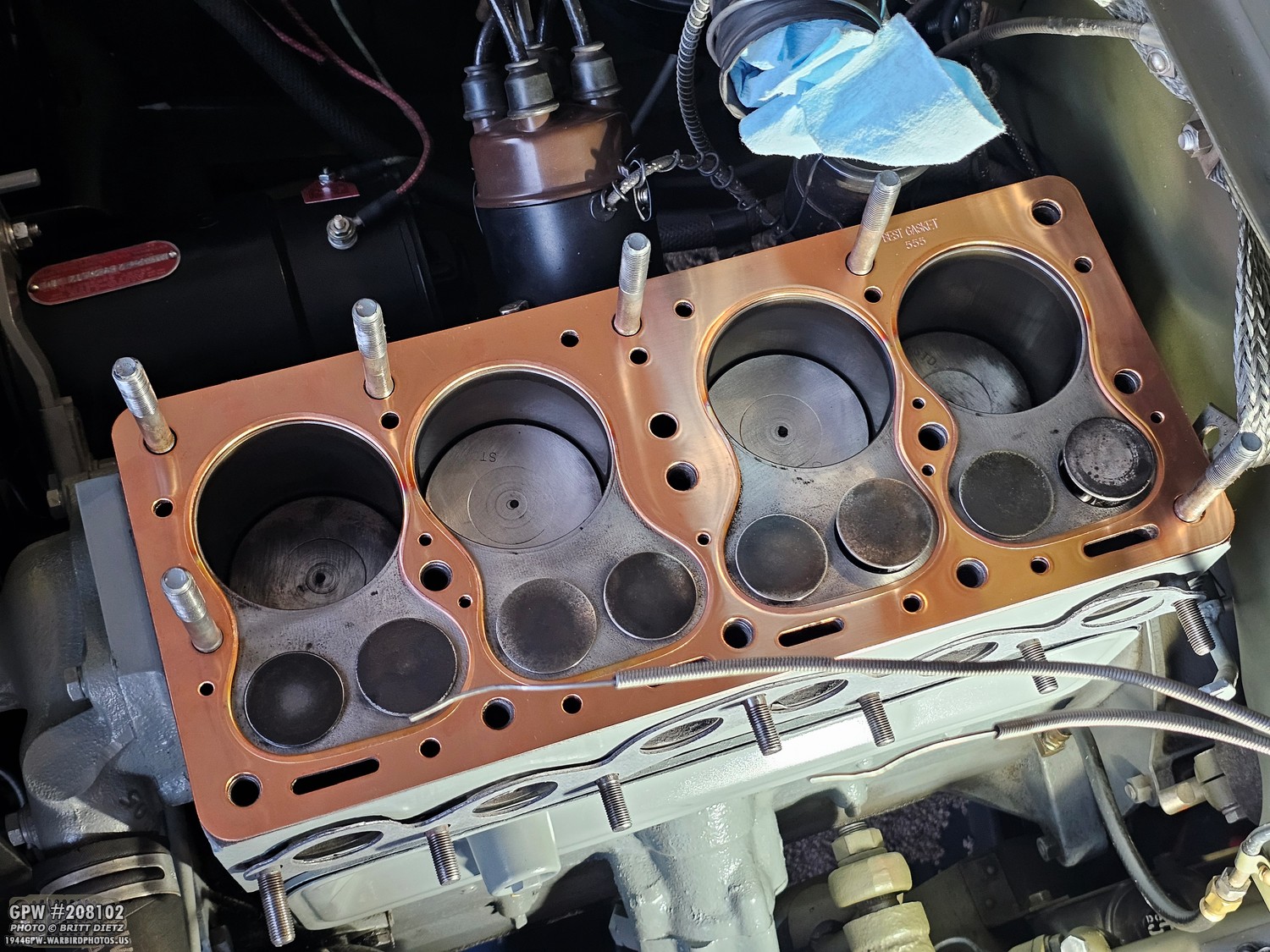
It’s always a good idea to dry fit the head gasket on before you install it to make sure everything lines up, especially the stud/bolt holes and the coolant holes. Check the valve clearances as well.
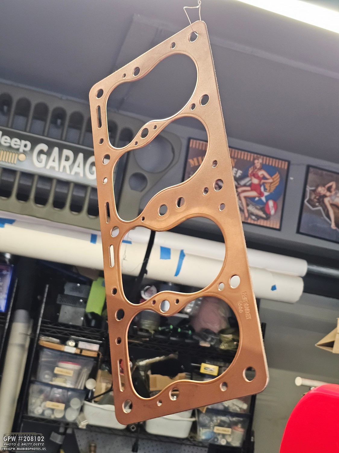
I wanted to make triple sure that there were no coolant/oil leaks with the head gasket, so I sprayed it with some copper gasket spray. You then let it hang to dry until it’s tacky (sticky), then it’s time to install.

With limited time to install everything, I didn’t get photos… but to add even more protection beyond the copper gasket and the copper spray, I also lined every coolant hole (shown here) with red RTV. Only a very, very slight smear around each hole. You have to move quickly as the RTV will dry fast. So only do this right before the gasket is installed.
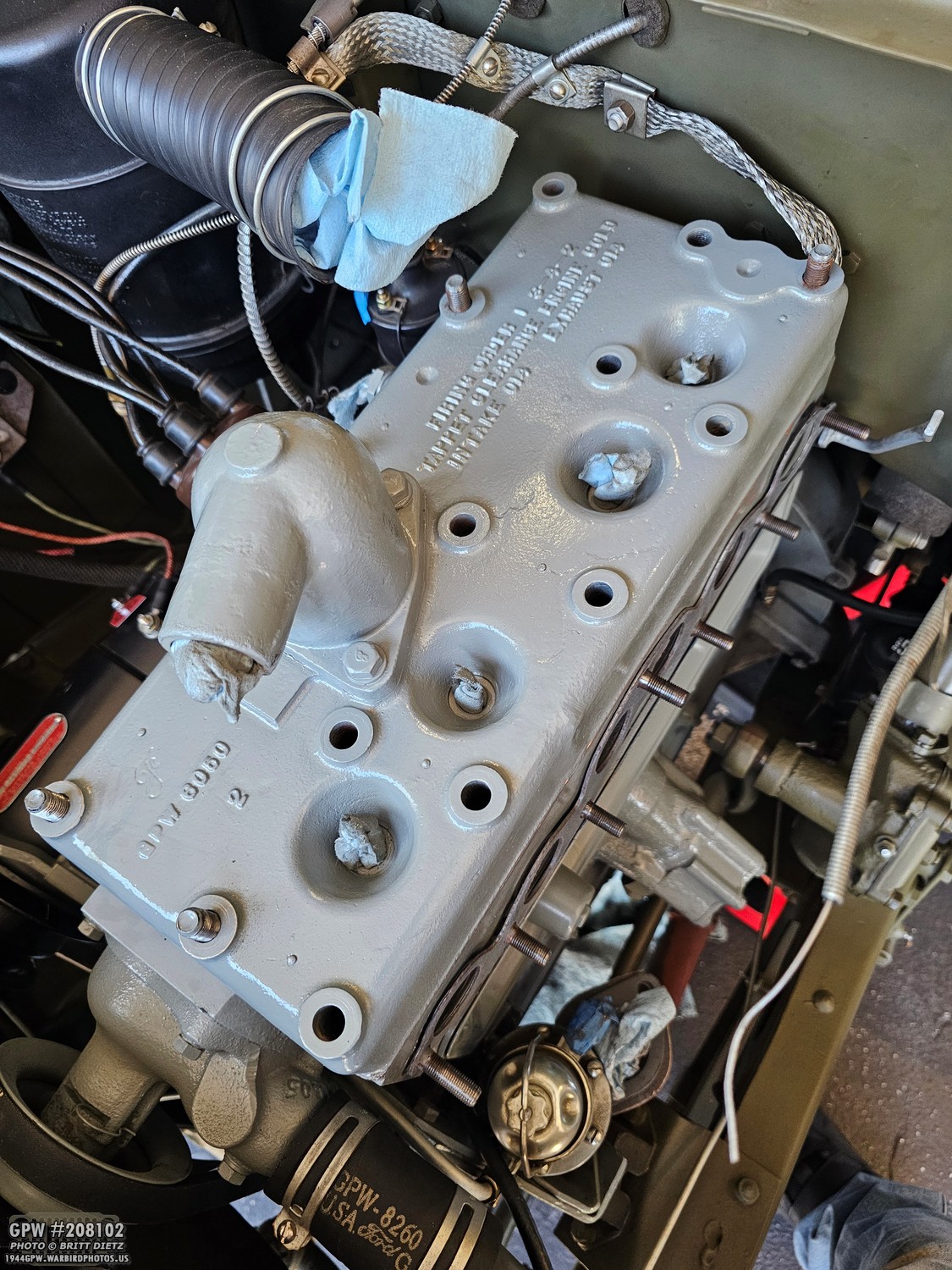
With the RTV slightly smeared around the coolant holes and the copper gasket tacky, I put it on till it was flat on the top of the block, then put the head on to give some weight. And this is where this update will end, as I’ve maxed out the images we can post on Facebook. Look for the next update next week, which will go through the rest of reinstalling the engine parts, torquing things, reinstalling the wheel and fender, testing the Jeep, and what I had to do when I realized .013 wasn’t the proper clearance.
Till the next update!
Till the next update!