 Small projects, Hood Finishing, and Axle work!
Lots of projects this week making for quite the busy work! I worked on various small projects that have been needing to be done, such as modifying a rear seat J hook to fit, prepping shock brackets with fake rivets, and replacing the combat rim valve stem protectors. Work on the hood continues, it’s all finished minus the markings! And I continue work on the front axle installing the RZeppa shafts, packing grease into the knuckle, installing the brake plates/drums, and adjusting the brakes!

A sneak preview of what’s to come in the update, it looks like I took a step back with the hood, but it’s an original hood vs MD Juan repro! Lots to dive into this week, so let’s get going!

I currently have an MD Juan body tub on the Jeep, which is there as my original tub needs extensive welding/reshaping work which will take a few years (especially to a beginner welder like me). So an MD Juan tub meant I could enjoy my Jeep and can take my time on the original tub. The MD Juan tub is not perfect, with many many flaws. One of them being that the studs for the J hooks on the rear seat are not right, meaning that I can only get one of the J hooks on. So my Jeep has been without one hook for the last year. Not a big deal, it just holds up the rear backrest of the rear seat, but it still bothered me.
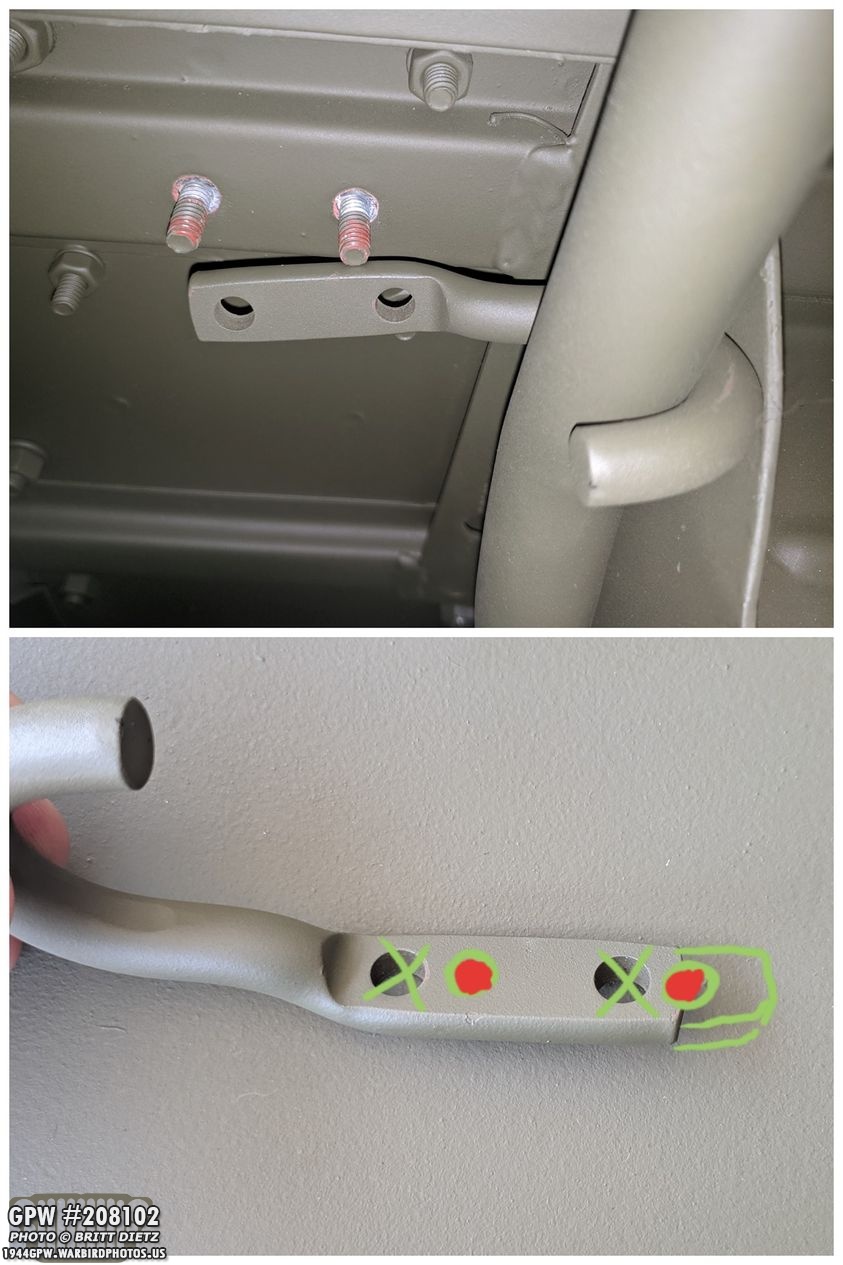
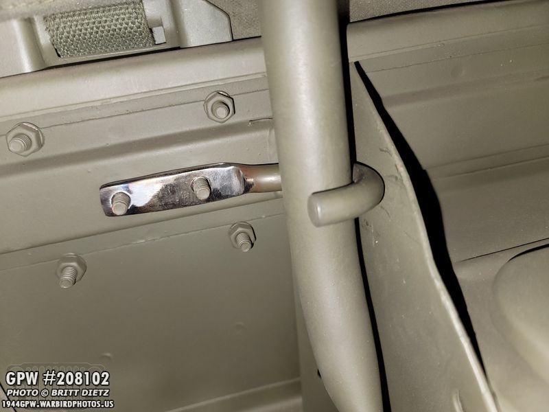
Here’s the problem, the two studs on the driver’s side are not in their correct position. They are too far towards the center of the Jeep, so when I put the J hook on the passenger side, which goes in fine, this side doesn’t line up, as you can see in the top photo. So I realized that, in order to get the second one to work, I’d need to extend one of the J hooks and move the holes outward more (as shown in the bottom photo).
Not wanting to ‘bubba’ original F marked J hooks, I got a pair of repro F marked J hooks to use.
So, this is how my Jeep has looked for the last year. Only one J hook (that’s the repro J hook on there, I just haven’t gotten to this project due to needing more welding practice). Again, not a big deal, but it bothered me that there was only one. No one has called me out on it in this entire year.

But this past week, I found myself with a day where I was waiting for paint to dry before moving on to a next step with the hood, so I thought… why not give this project a try? So I got out my other repro F marked J hook and proceeded to remove the paint around the end. I make sure it was totally clean of all paint.
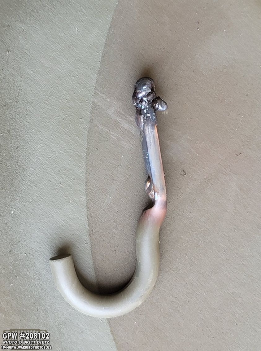
Using the welder, I welded up the holes and I slowly added gobs of metal to the end of it extending it outwards. It looks messy now, but I wanted to make sure I made the extended area thick enough. The welder worked amazing with this thicker metal, and the new metal went on beautifully.
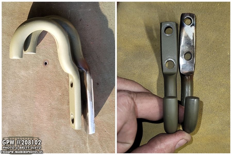
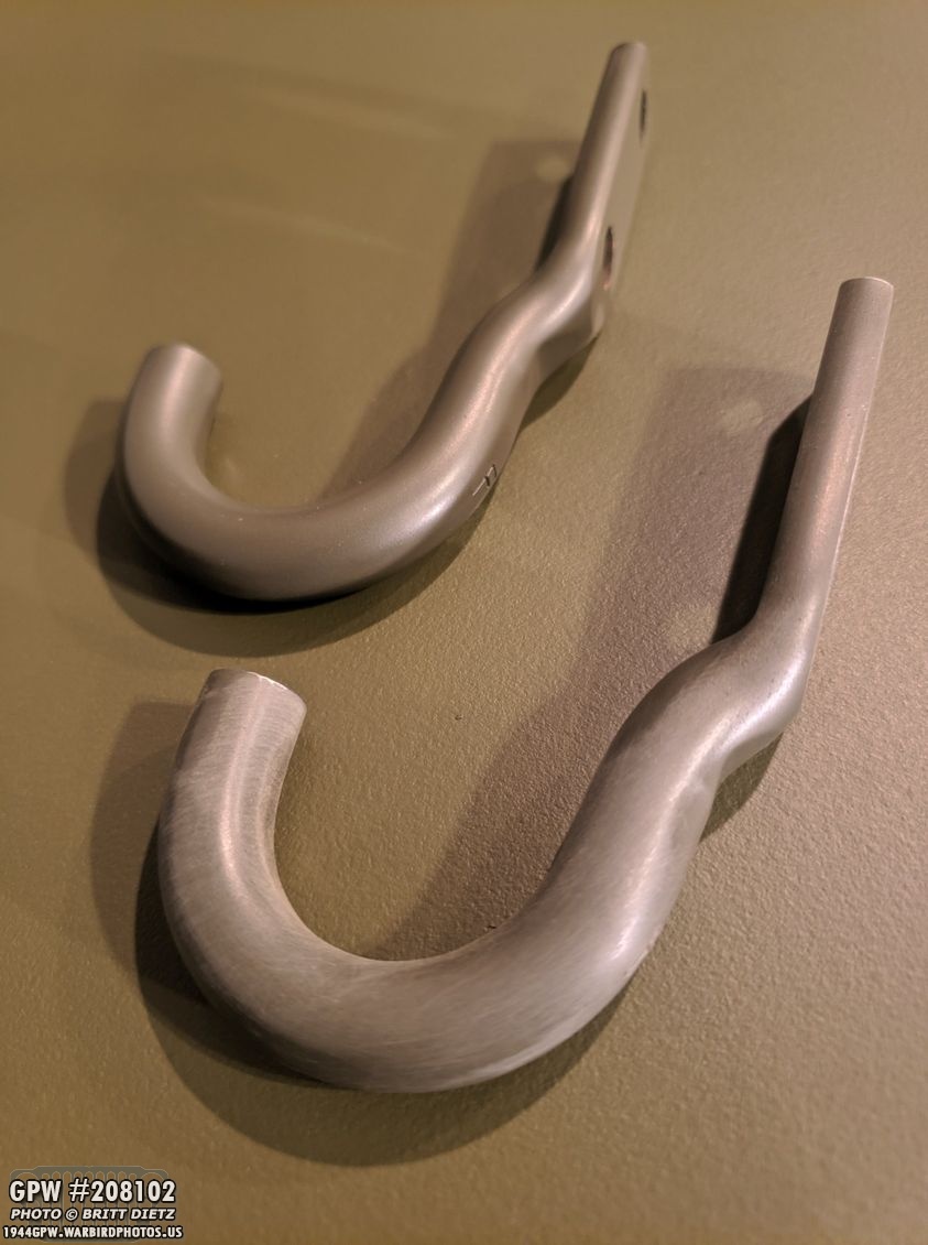
I then took a combination of a flap wheel on an angle grinder, Dremel, belt sander, a metal file to slowly smooth out the welds. I’m not perfect at shaping metal, but I think I got it pretty darn good (left photo). I tried to match the same shape as the other J hook (which I took off for reference). Drilling the holes was a PAIN. Took hours to drill through it all, and I think I ruined at least 5 drill bits. That was not fun, that metal was thick and did not want to drill. UGH. But I finally got the holes drilled. So, now the test… did I drill the holes correctly?
Success on the holes! YAY! But, can I put the other J hook in and have them both successfully on? That’s the real test…

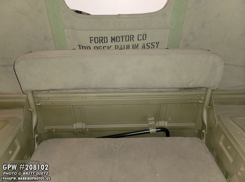
SUCCESS!! Both J hooks work! It’s a bit tight, but they lock down perfectly. Anyone who has ever had an annoying detail like this that they had to fabricate a custom piece knows the joy you have at that moment when you test it and it works just like you hoped!

I then went on to painting, hitting it with &Ron Fitzpatrick Jeep Parts Red Oxide Barrier III primer. Already, it starting to look like a normal J hook.
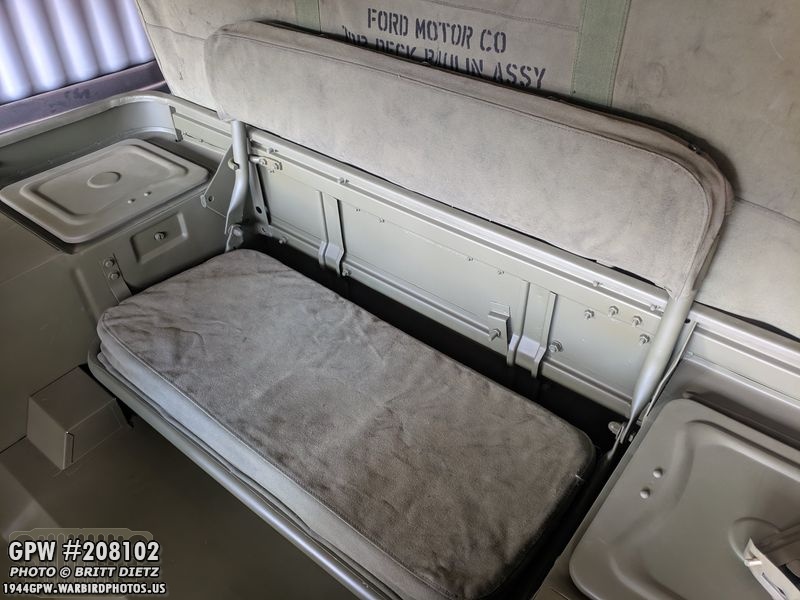
After getting 33070 OD Green painted, here it is installed! The subtle difference between the two is so minimal when painted, I don’t think anyone will even notice even if they were looking at them both.

And now that it’s painted OD Green, it’s even harder to tell it was a custom job.

So there we go, another little detail fixed! I know, this is only temporary as the original tub has the studs in the correct spot, but I know it’s going to take at least a year or two for me to fix the original tub, so this project hasn’t been a waste of time. Now, had I elected to try and move the studs over instead of elongating the J hook, that would have been a waste of time as that project would have been quite the undertaking. But I’m happy with it and my welding work!

Moving on… my Jeep is missing the rear shock mount brackets on the frame, which is why there’s such an empty space between the shock and the body tub. These brackets were removed at some point, but the front ones are still there. Whoever removed them also put a large bolt through the lower shock bracket hole and mounted the shock on there with a nut on the other side. This actually raises the rear of the Jeep by about 4 inches, so it’s something I’ve wanted to fix when I replace the axles.

Earlier this year, I managed to get a pair of shock brackets that were in very rusted shape. Turns out, it was only surface rust as they cleaned up amazingly well. Like night and day, and this example I’ve used many times when showing people how even the most rusted looking things can be made near new looking with some effort!

They’ve been primed and painted OD Green for months now, just waiting for installation. I could have installed them any time, but I was waiting as I know when I replace the CJ axles with the wartime GPW ones that are almost finished, I’ll have a lot more access under there to get them installed (I have to weld them as well, so the more room I can get the better.)
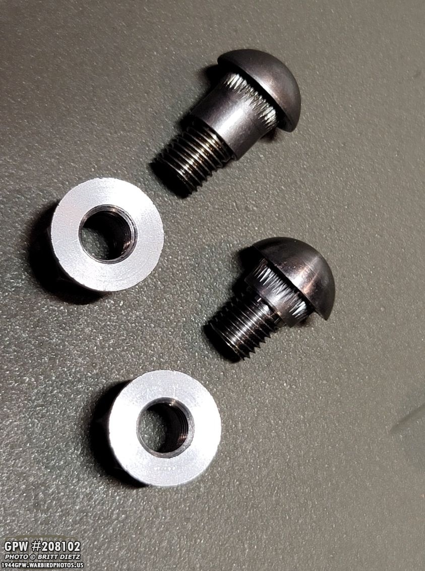
I don’t have a way to rivet them, so I’m using the ‘fake’ rivets that I used on the seat pivots a few updates go. These will work perfectly. They come in two lengths, so for this, I wanted the longer length (top). These are heavy-duty screws that on one end have a smooth rivet head with teeth on the shoulder to keep it from spinning when driven into the hole. The other side (which you can’t see well in this photo) has the other side of the rivet head and an attached nut, which when you tighten it to a certain torque, breaks off cleaning the other rivet head.

The problem is, the holes are too small in the bracket! So I reached out to the seller on ebay, and finally got a reply back that the hole size needs to be 3/8, so I’d have to drill these holes larger.

Before I drill them, I test fitted which rivets would go where. I can use the shorter rivets on the bottom hole, but the two side ‘flaps’ need the longer rivets as these multiple layers of metal.
And here’s a closer look at the problem, where the hole is large enough for the thread part to go through, but the shoulder area is too large. So time to start drilling!

3/8 worked mostly, but I found that I needed to take my Dremel and open it just a bit more to get it to slide all the way to the teeth. I’ll drive those teeth in a bit before I instal the brackets, which I hope to do in the next few weeks as I begin the axle-changing project.

The last thing I needed to do in prep is wire wheel the back area, which is welded to the frame. So I wanted to make sure I had nice clean metal to weld. Again, this is one of the major reasons I waited to install these, as I’ll have to be welding while underneath the Jeep jacked up. Not going to be much fun with the close quarters. Thankfully, it’s under the Jeep and doesn’t need to look pretty, so that will help me go quicker with the welding. I’ll have to wire wheel that area on the frame as well.
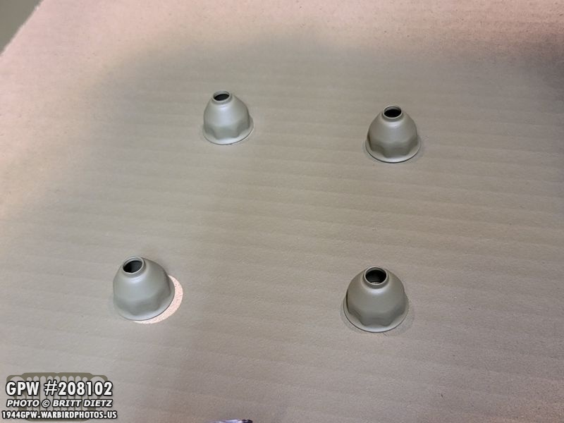
Next project, I recently was doing some research on combat rim valve stem protectors, and I came across some wartime and NOS photos online and realized the ones I had were not entirely correct. It’s a small issue, again most people wouldn’t even notice, but it bothered me. So I ordered a set of the correct style (4 of the 5 shown here). What makes them different?

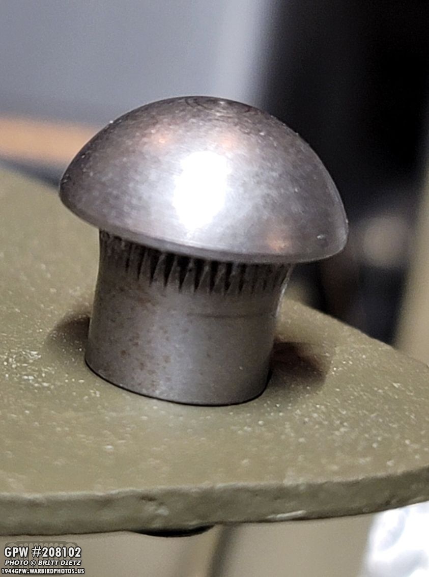
Here’s a look at the two. On the left is the set I had on my combat rims, and on the right is the new set that is more correct. You can see the ones on the left are more of a bulbous round shape, while the right one is more pointed. The more accurate right ones are made by MV Spares. For most people, either one is good enough… but it was just a small detail that bothered me.
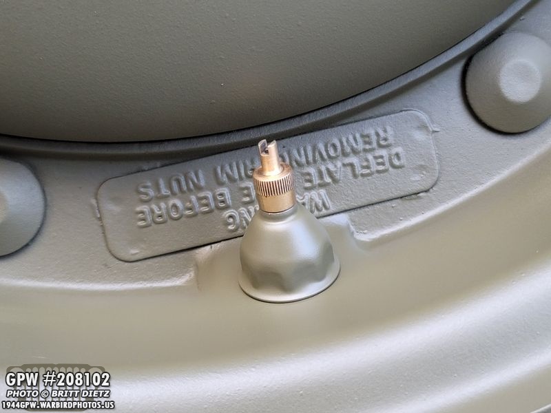
Here’s the new style added to the combat rim after some touch-up paint! A much closer look to the original style from the wartime photos. I could have gone a step further, as Peter Debella has them with the SHRADER markings on them, but once you prime and paint them, those markings are almost impossible to see anymore, so it’s not worth the extra money unless you are going for uber factory correct.

I then took the time to replace the protectors on the other four tires which are waiting for install once the wartime axles are done.
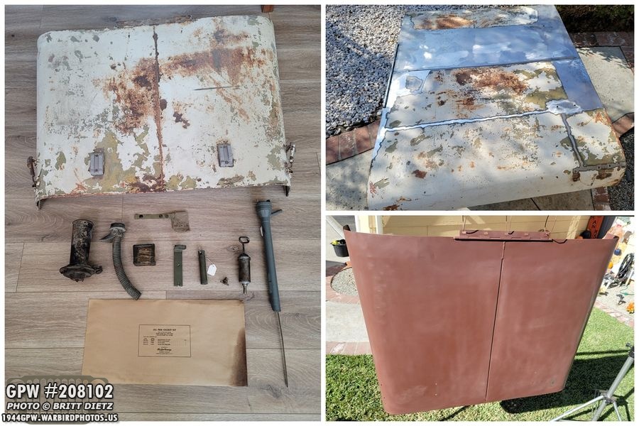
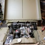
Now on to the first of the major two projects for this past week, the hood! A quick recap… my original hood was too damaged and rusted to repair, it’ll be a wall decoration. I’ve had an MD Juan repro hood on the Jeep. I finally found an original 1943 GPW hood at a ranch selling military vehicle parts, and for the last few weeks I’ve recovered the original hood numbers (see last week’s update), and been removing the paint (sandblasting was too expensive with what I was quoted). It was then primed with the red oxide primer.
I finished last week’s post with a look a the hood finally painted 33070 OD Green (&Ron Fitzpatrick Jeep Parts gallon paint with sprayer) with 2 layers of paint.

Before the third and final layer of paint, I wanted to attach the accessories. So I began taking them off my MD Juan hood and putting them on this hood.

That includes my original GPW hood latches and catches (which were taken off my original hood). I took some time to sand the paint down in areas where it was buckled or scratched from taking it off and putting it on. And yes, I have F stamped 1/4 bolts for the catches. Many say it never happened, some say they had them on theirs. I like how they look, so end of story!
I then took off my MD Juan hood (anyone want to buy it off me? All painted with star and numbers/usa!) and I sanded some of the areas on the cowl where the hood attaches that got scratched up this last year it’s been on.
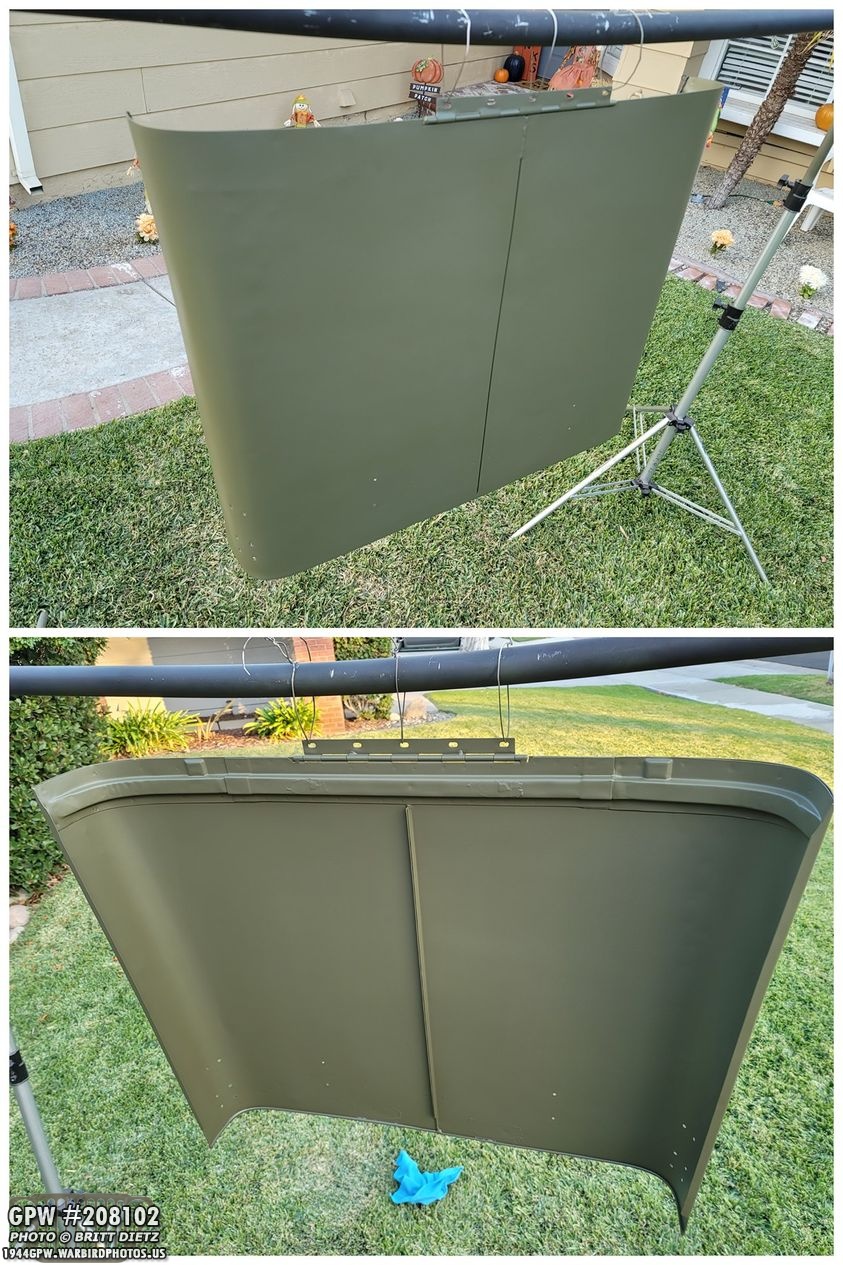
And here’s the third coat of paint drying with the hood blocks and side catches on! Paint job came out beautiful!

And here’s a look at the catches on the outside and the inside. The curved reinforced plate on the back is also original from my original hood.

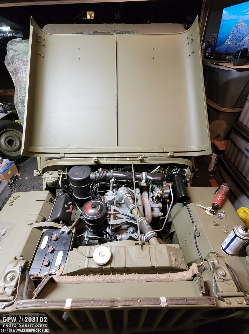
After that had dried for several hours (the 33070 OD Green paint from Ron Fitzpatrick Jeep Parts and Xelene paint thinner dry so fast, it’s amazing!) I went ahead and put the hood on the Jeep! With the help of my girlfriend, it’s really tough to hold the hood and install it at the same time. It took some moving it left and right (the holes on the hood hinge are slightly slotted so there’s some room to move the hood for the best alignment).

Right after I closed the hood and reopened it, I noticed a problem… the area of the hat channel I’ve worked so much on trying to fix cracked… AGAIN! Ugh. That metal just doesn’t want to stick and fuse. It’s just so thin. And I probably made it thinner than it should be since I was trying to mimic the original shape of the outer channel going under the middle channel.

And then I realized WHY it cracked, the rear of the hood was actually making contact with the side of the body tub, as seen here, which forced the channel outwards causing it to crack. UGH. So what I did was move the hood over a little more and slightly bend out the channel a little more to pull it away from the side of the tub.
Once I did that, the hood was pretty good. It didn’t seem to be hitting anywhere else, and it closed and opened well. I still need to fix that crack, and also sand/paint the area of the tub that was scaped, but I was feeling good about the hood.
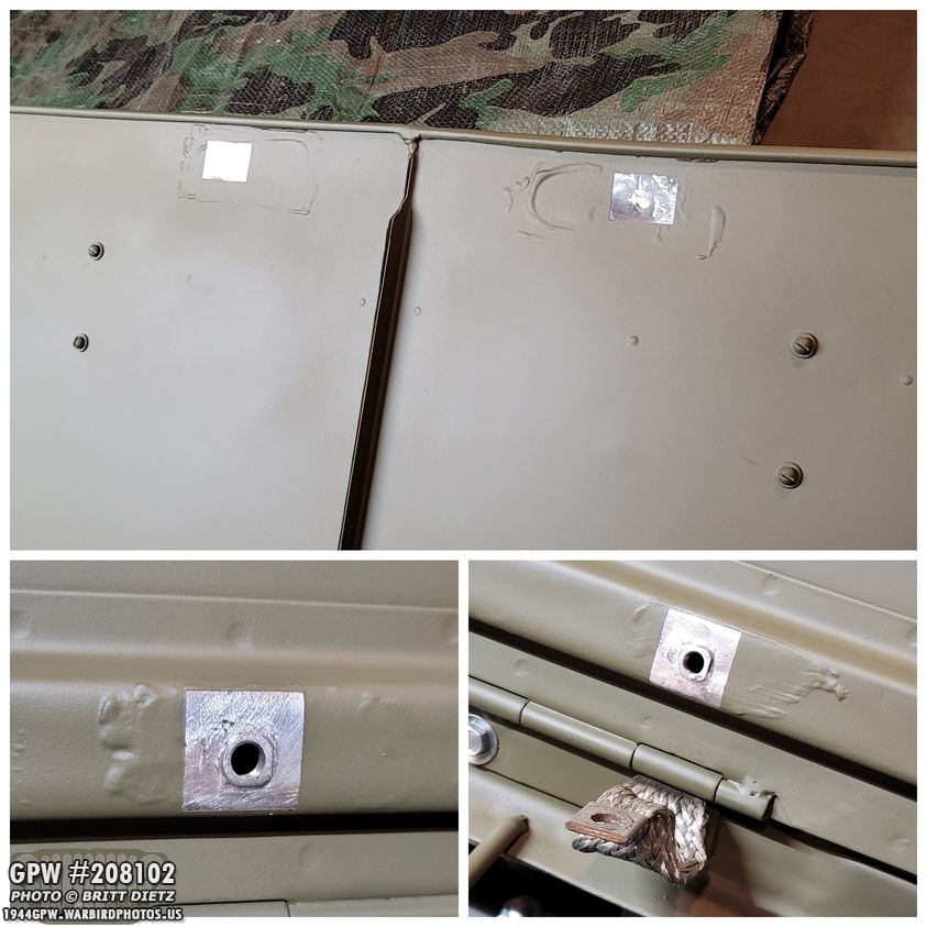
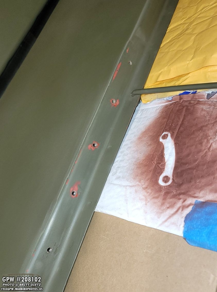
I then peeled off the painter’s tape that I put on before I started painting the hood for the suppression tinning. (see update last week). It worked well, nice clean lines. I know in wartime they often just slapped some grease on there, painted the hood, then wiped the grease off which took the paint off, but I wanted something a little nicer. Let’s call it a day that the worker took pride in his painting of a Jeep on the assembly line! The top photo is the two spots where the grill mounted bond straps contact the hood (which I figured out where that was via putting some white water-based paint on the bond straps then closed the hood when I initially tested fitting it).
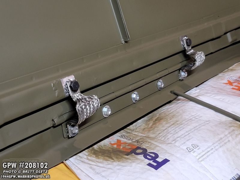
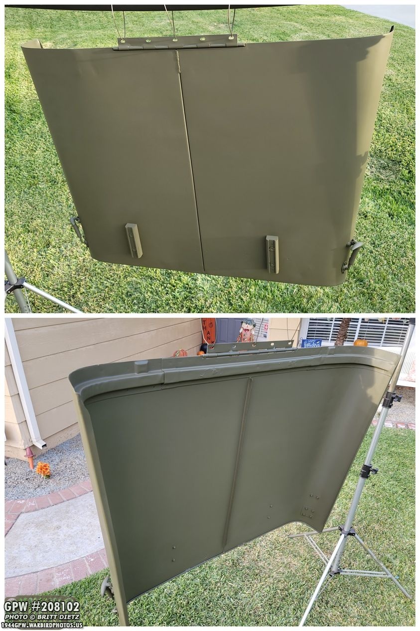
And here’s the two bond straps installed! The tinning square looks great underneath them.

And with that done, all that’s left is to take it on a test drive to make sure everything stays put and the hood doesn’t have any issues.

I also readded the asphalt strips to the hood blocks. I turned them over and used the underside as the other side was starting to look faded.

And the next day I took the Jeep out for a spin with the new hood. It’s weird not seeing a star on there. Worked great, the engine seemed a bit quieter (the original hoods are much heavier and thicker than the MD Juan repros I’ve found) and there was less rattling than before.
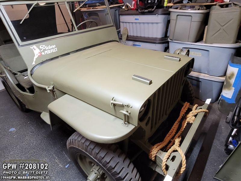
So I’m chalking this GPW original hood up to being DONE, just needs markings (which are on their way right now!). I’m happy to have an actual GPW hood back on here with a lovely F stamp on the hinge rather than the generic unmarked MD Juan hood. On less repro item on the Jeep!
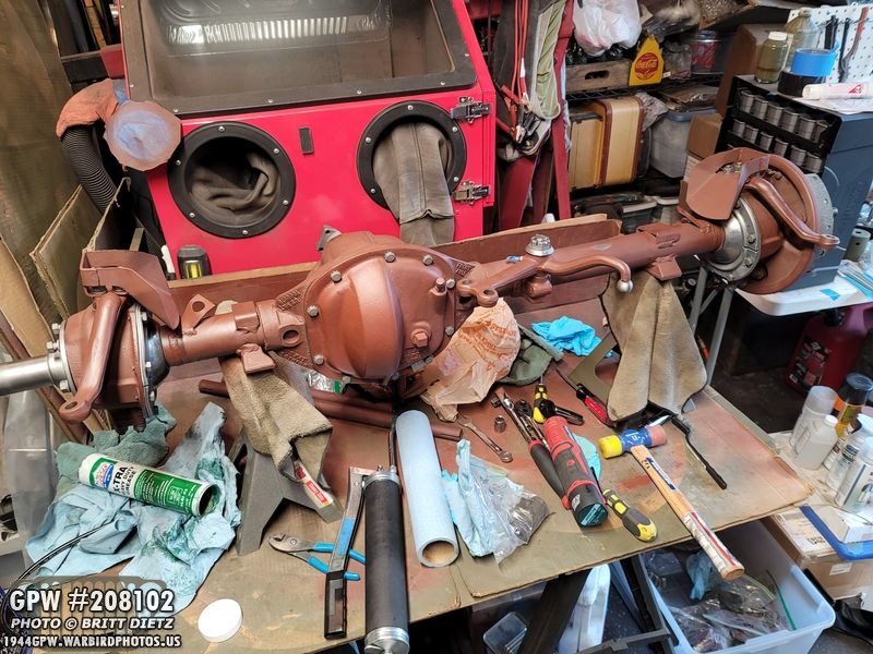
Moving on, last week I was starting major work on the front axle. Short recap… my Jeep has CJ (post-war) axles on it, how I got it. I was given free two 1943 wartime GPW axles that have taken me most of this year to totally take apart, get all the parts needed, clean/restore, and now I’m putting them back together to replace the CJ ones hopefully soon. Last week I put the knuckles on, showed how to install the kingpins and check the proper strength, and installed the dust shield using a mix of the newer modern replacement kits and the original shields.

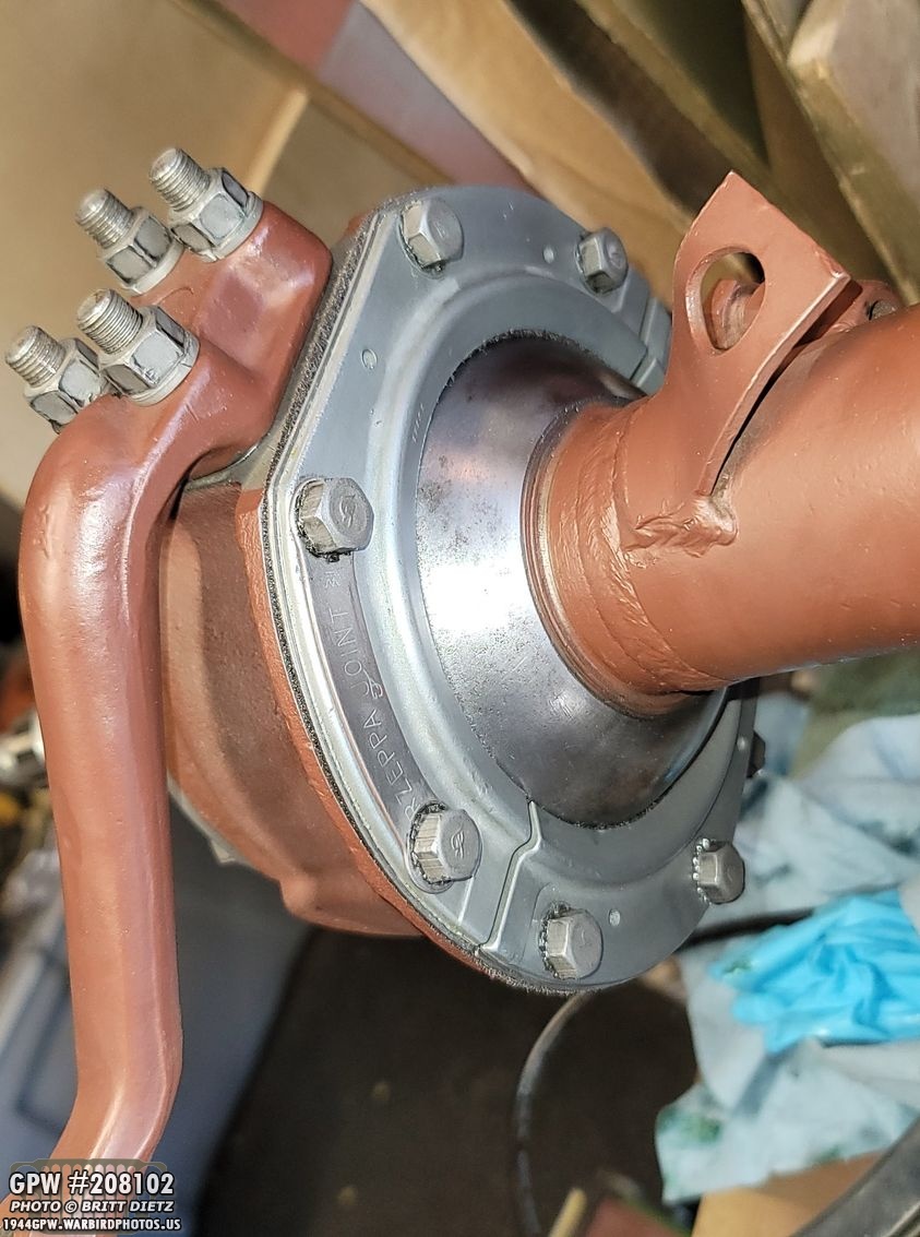
Before I moved on, I hadn’t yet installed the brake line shields, so I went ahead and did that. 95% of the parts on this front axle are original to this axle, so these shields have nice GPW/F stamps on them.
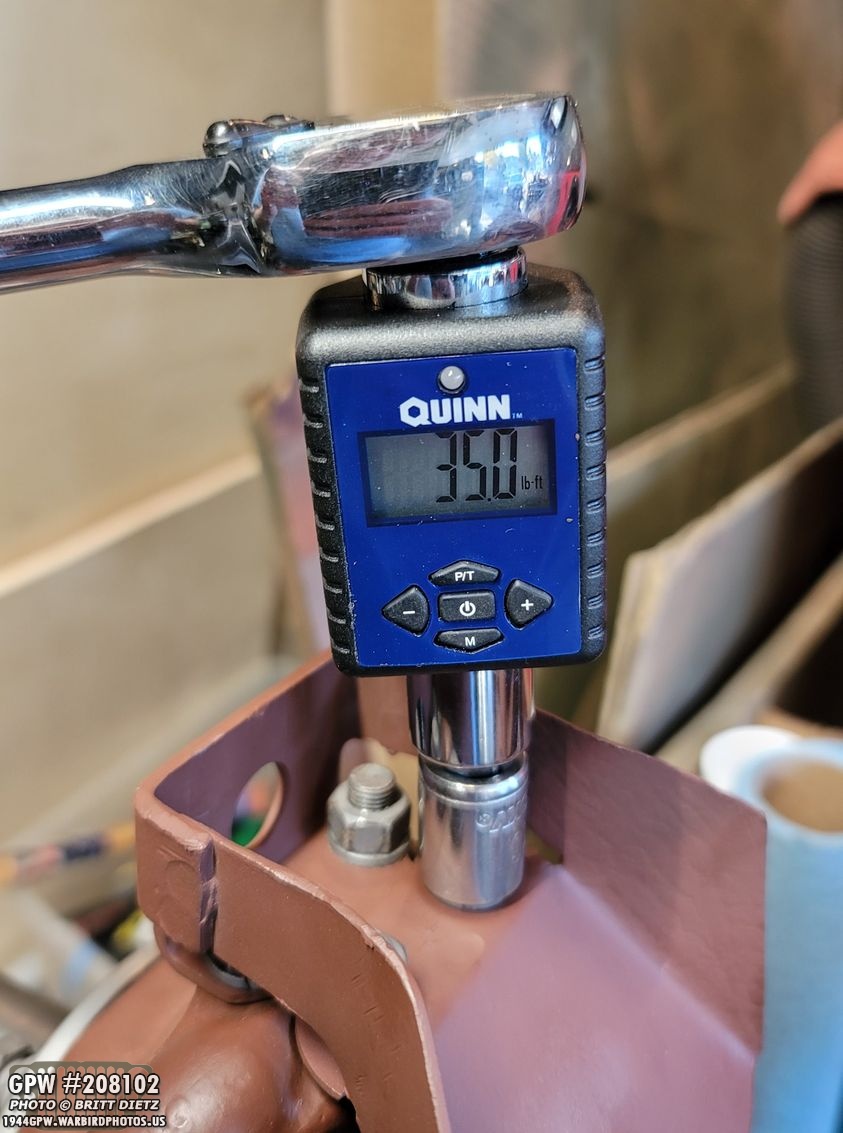
I made sure to torque down the nuts at 35-foot pounds.

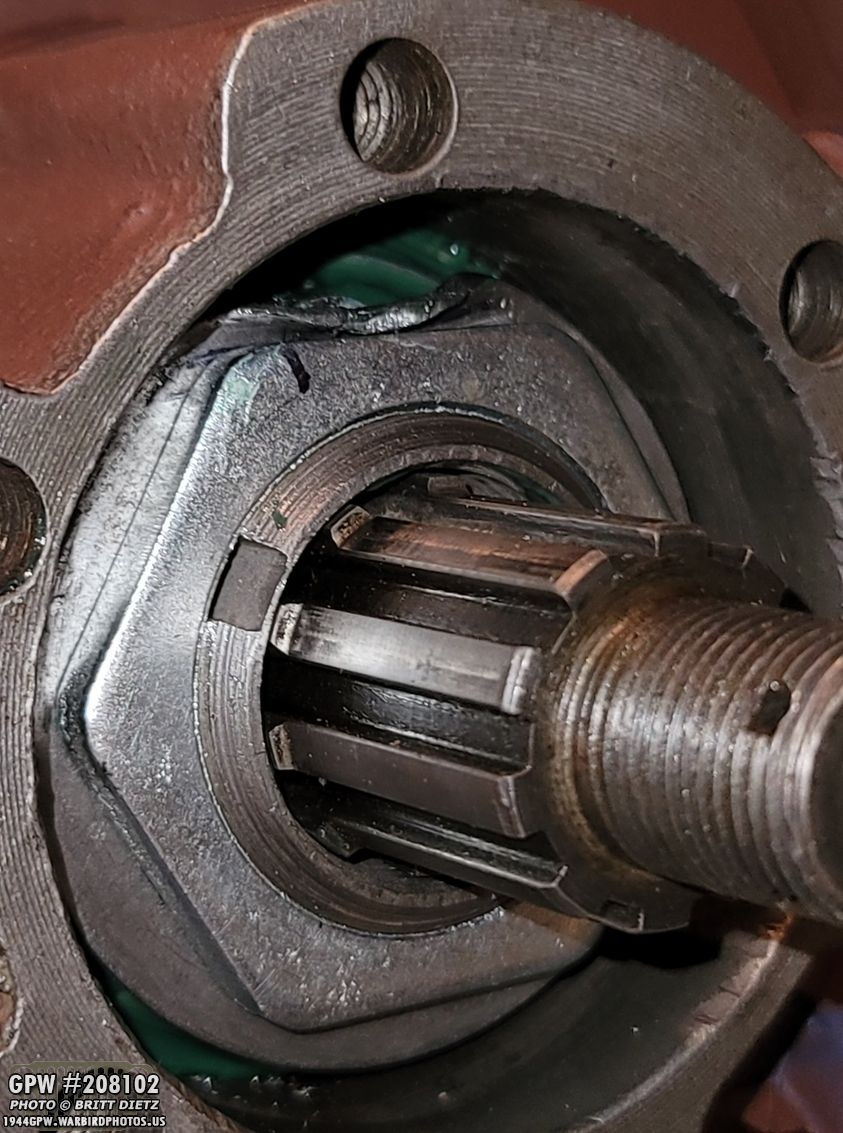
Now I could move on to inside the knuckle. Lots to do here! Need to add the axle shafts and pack it with LOTS of grease.

First up, packing the RZeppa axle shaft with grease. I used my grease gun and slowly rotated the shaft around the cup filling in every little pocket that would appear between and around the ball bearings with grease. I didn’t stop until the grease was oozing out of the ball socket holes. I then added some grease on the flat metal ring area where it would be riding on the internal oil seal.

Once the RZeppa was in the knuckle, I then went to work packing in grease. This takes a lot of time. I used my grease gun and slowly pumped grease in side all around the RZeppa. You want it in there so much that it’s almost oozing out the screw holes as seen here. I also put grease on the metal ring on this side, as it would be riding in a bearing in the spindle.
I skipped forgot to take a photo of the spindle installed, but that was the next step. It goes over the knuckle and then the brake plate goes over it. You affix them all to the knuckle with the 6 bolts. If goes quick, as to install the spindle it needs the brake plate, so that’s the reason I didn’t get a photo. Make SURE the bolt holes do not have any grease in them. These bolts (original) don’t have F stamps on them as the rear axle ones did.
The driver’s side axle has the plate, but you can just barely see the passenger side has the spindle on but not the brake plate yet (which I have the bolts partially screwed in just to keep the spindle on). It’s a lot of tools to do all this, and a lot of grease!

One thing that really helps is to have a ORD 9 with the break down of everything nearby. This is my original 1949 ORD 9. The repros you can buy work great as well, or even download them free online (like at jeepdraw.com) and print out those pages.

With the brake plates on, I could then put the drums on! But they needed to have bearings and cups reinstalled. My plan was to use two of the original bearings, which were in good shape, and two new sets. I found, at a garage sale, a new Timken cup and bearing set, so I started with that.

By now, you know the drill. I’ve covered it extensively with the rear axles and kingpin bearings. I drove the cup into the drum, packed the bearing with grease, put it in the drum, and then tapped in the oil seal. I also put some grease on the oil seal lip as it spins on the spindle.
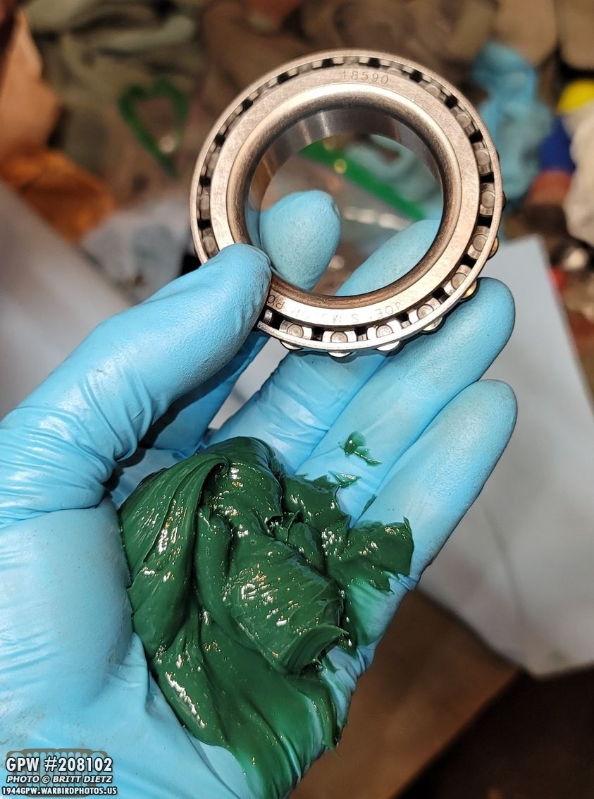
For the other side, I used one of the Joes Motor Pool cups/bearing sets from &Ron Fitzpatrick Jeep Parts. Same thing, packed the bearing with grease after installing the cup in the drum.

Then pushed the bearing on the spindle back into the drum. I then installed the first smaller washer (a new one, as the original was in bad shape).

After installing the first spindle nut, I went to install the larger washer and remembered that this was one of the ones that needed replacement. As you can see, the original was really beat up. I’d ordered new ones (along with new spindle nuts since all were beat up).

And as before, I installed the large washer, then the last spindle nut. As with the rear axle, I tightened the nut nice and snug, then marked one of the sides of the nut with a sharpie on the large washer. I then unscrewed the nut and took back out the larger washer.
That allowed me to ‘pre-peen’ the large washer along the sharpie line I drew so it would be easier to peen all the way down on the side of the nut once I put it back online. Once it was back together, I used a flat punch tool to ‘pry’ the washer down so it locks the nut in place, as shown. Make SURE you use the thicker side of the drum flange when prying! You can see the marks where people in the past have wedged something to peen the washer.

There were no shims on this side (which I’ll talk about in a few photos when I get to the other side), so I went ahead and added the paper gasket.

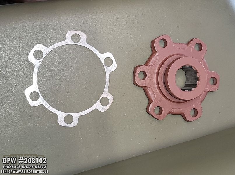
Finally, the outer drive flange was put on. You can see the partial F stamp in the 11 o’clock position.

This side was missing two F marked flange bolts, so I added two repros to complete the set.
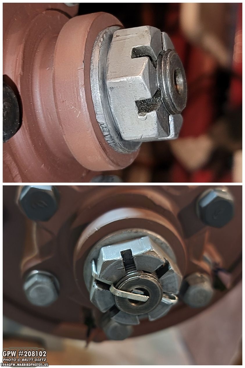
Then I added the spindle washer and the castle nut. Roger Smith mentioned, on a phone call, to check for any play (which is the reason there might be shims). I did this by grabbing the castle nut and trying to move it forward and back. But it was locked very well. Finally, I added a cotter pin to lock it down.

On to the other side, it was the same process, starting with the brake plate and spindle.
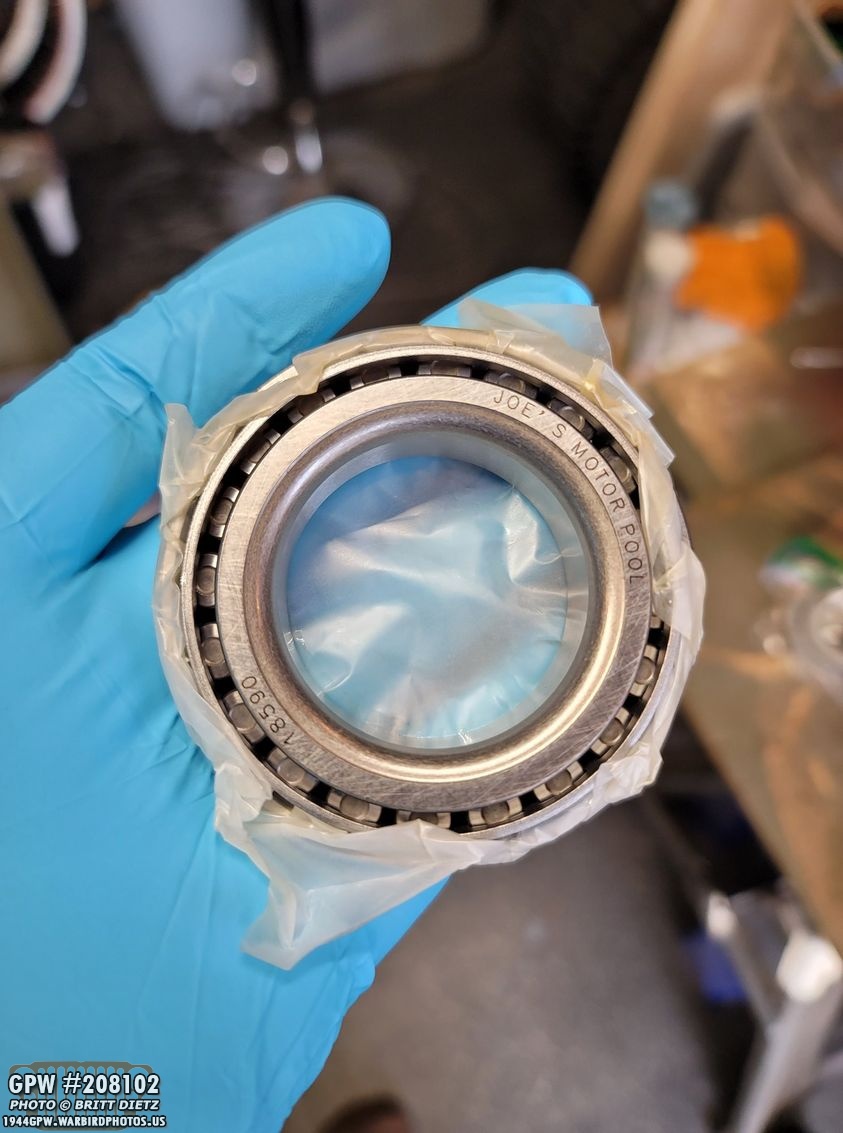
I originally, as mentioned, was going to use two of the original bearings. But finding that Timken set at the garage sale meant I only needed to use one. Well, sitting in a box for a few months made the bearing freeze in place, and I couldn’t seem to get it to move well. So I went ahead and ordered another Joes Motor Pool bearing/cup set (shown here). So I have all new bearings on the entire axle. Probably a good idea for safety anyway.

Same thing I’ve done now four times, installed the cup, packed the bearing, installed the bearing, installed the oil seal on the inside of the drum.

After installing the other cup/bearing, I repeated the same process of adding the small washer, the first spindle nut, adding a new large washer and the outer nut, marking a line, taking it off, pre-starting the peening, then putting it back on and peening it down against the nut.
So on this side, there was a thick metal shim, shown here (F stamped too!). Again, this is to stop any play on the RZeppa axle shaft and keep it in place.

I added the paper washer on top of the shim as shown. I guess it could go either way.

And then the drive flange. This one had two missing bolts as well, so I added to repros. You can see the Fs are a bit different between the repros and the originals, but it’s close enough. I guess, technically, I could have made my own F marks using the method I described two updates ago on making your own F stamps.

The RZeppa was nice and locked in place once the shim was on there, so I added the spindle washer and castle nut. Finally, the cotter pin (not yet bent).

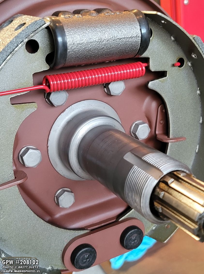
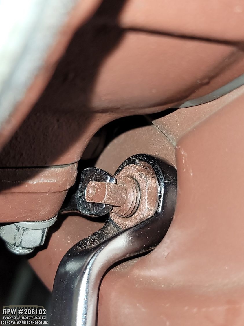
With the spindle/knuckles/drums done, it was time to adjust the brakes! I won’t go into depth on how to adjust the brakes as I did that for the rear axle. Search about 3-4 updates back for how to adjust them. But the front axles have a major difference vs the rear axles… the lower kingpin arm on top and cap on bottom make it VERY tough to adjust the brakes. Especially the bottom anchor pins, shown here. That kingpin cap is so close, I couldn’t get my curved wrench in there.

I had gotten these offset wrenches from Harbor Freight Tools, which worked perfect to tighten the large nut on the anchor pins on the rear axle, but for the front, I’d need to make a modification. On the right photo, you can see I took the wrench to my belt sander and ground off about 1/4 to almost half of how tall it was. I also smoothed out the edges so they wouldn’t catch.

This meant I could finagle the wrench to get through the very tight space and get over the nut. Success!

After adjusting the brakes on the passenger side first, I went ahead and installed the F marked original dust shield! All done and ready for paint!
I moved on to the driver’s side, adjusting the brakes using my modified tool and the 1/4 wrench, all shown here.

I hadn’t installed the drain plug for the axle housing, so I got to work on that. I used some Permatex thread sealer on the outside threads to help keep oil from leaking out of the housing. I then used a 1/2 rachet to tighten it in place. The 1/2 rachet head fits perfectly in the drain plug socket.
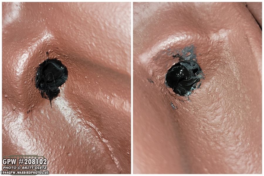
Finally, I used black RTV gasket maker to seal up the rear holes where you can see the ends of the inner differential cap screws. That will also help any oil weepage that might happen from the screws.

So, we’ve reached the the end of this week’s update. Next week, look for the installation of the tie rods on the front axle, painting the front axle (I hope!), and fixing the crack in the hood channel. If all goes well, I might begin the process of replacing the axles! Fun stuff!
Till next week…