 Finishing up the Transfer Case and rebuilding the Emergency Brake!
In this week’s update, I finish up the transfer case rebuild adding the yokes and the external emergency brake. I also explain how to adjust the e-brake according to the TM manuals. Finally, I finish off the T-84 Transmission with a new second gear and get repairs done to the cover. Also, some goodies that have arrived in the mail the last few weeks!
As with the last few weeks, these updates are about a week behind, and while this past week I actually have put the transmission back into the Jeep, this update will be the step just before that. I’ll leave you in suspense on how it all turns out!
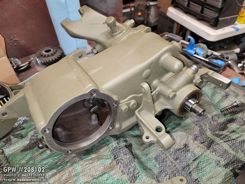
Recapping last week’s update, I finished the main rebuild and shimming of the D-18 Transfer Case. With all the bolts installed, gaskets for the output cap and the e-brake bracket installed, the next step was touch up painting!

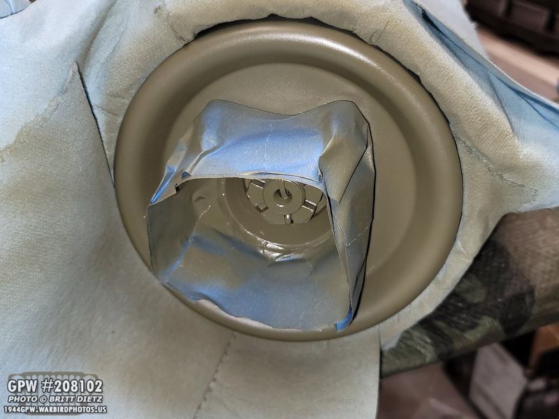
I masked off the various shafts and open areas on the case and gave it another coat of paint. This will help to seal the gaskets and shims along with the RTV. I put on a relatively heavy coat to make sure it’s all sealed well.

With the masks off, it’s time to install the safety wire on the bolts. The idea behind the safety wire is to prevent the bolts from unscrewing with the Jeep vibrations. Holes are drilled into the heads of the bolts (usually two so you have options depending on how the bolt ends up tight), and the wire will go through the heads so it’s always pulling the head to the right via the tension on the wire. I went out and got 16 gauge wire spool from Home Depot, which is well more than enough for this.

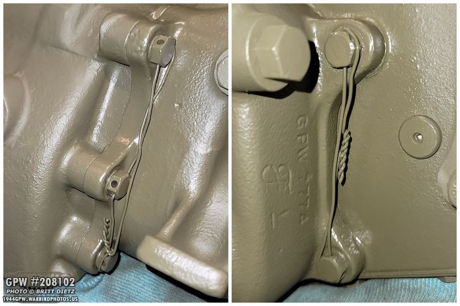
Here’s how the wire looks once it’s all tightened and the ends spun together.
After some quick paint, here’s how it looks. Here’s an easy way to see how it works. The wire is always pulling the heads to the right, clockwise. This will prevent the bolts from rotating left, or counterclockwise.

Time to install the safety wire on this side, you can see the three bolts on the left with the holes drilled in the heads.
Same principle with the bolts on this side. The wires are pulling the heads to the right. Here both side of the output cap are after touch up paint.

Now it’s time to add the emergency brake parts! My Jeep is part of the last few to have the external e-brake setup before the internal e-brake style came into production for both Willys and Ford. Here are all the parts (minus the drum and band) for the external e-brake.

The linkage for the main arm can be a bit confusing to put together, but each piece is set up this way with cotter pins and clevis pins. Make sure to grease up the clevis pins as you insert them!
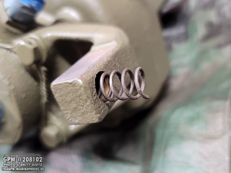
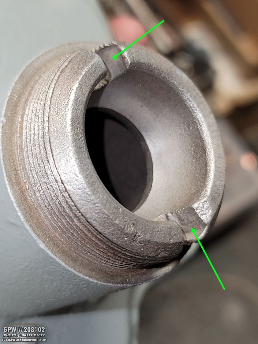
Before we can add the linkage to the e-brake bracket, we need to add the outer band. To do that, first you’ll need to enter the spring into the e-brake bracket that’s on the transfer case. It fits into this little hole on the side arm.
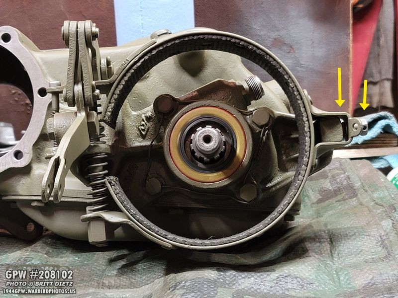
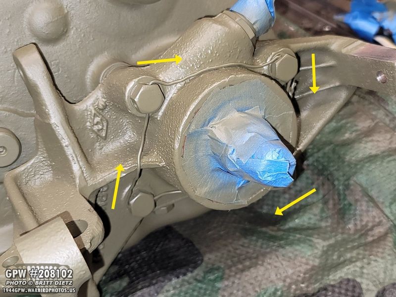
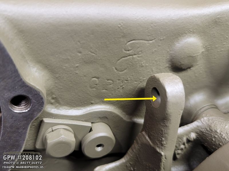
(ignore the linkage already on, I forgot to take a photo showing the band being put on). When placing the outer band on, compress that spring you just put into the arm hole, and push the band over that arm (left arrow) so the spring is between the bracket arm and the band. Insert the side anchor screw (right arrow) so that it goes through the spring.
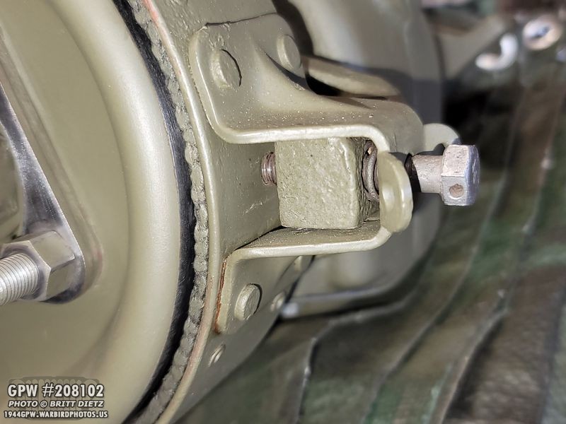
Here’s a little better photo showing the bolt going in the side of the band arm, through the spring, and through the e-brake bracket, and then hitting the other side of the band. This screw will push the band on this side closer to the drum.
With the band installed, we can install the arm linkage! We will start with this hole on the e-brake bracket.

With the final clevis pin, grease it up and add the linkage with a cotter pin.

Here’s how it should look.
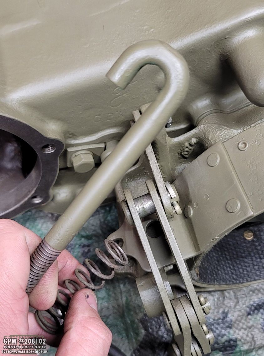
Now we’re going to add the J hook bolt. This is a bit tricky, because as you add it, you need to carefully insert the two large springs. See that clevis pin in the middle of the image that has an open area where the two arm linkage pieces are spaced out? The J part of the hook bolt will grab onto that pin.

Here you can see the bolt installed, with the springs in between the band ends and the J hook grabbing onto the clevis pin. I have the linkage arm rotated backwards for this photo. It’s best to slowly install the J bolt, add the first spring, push down on the J bolt, then add the second bolt once it passes through the e-brake bracket.
To lock the linkage arm in place, you’ll need the large bolt with the shoulder. Put some grease on the shoulder as the arm will pivot on it.

And then insert the bolt this direction through the arm linkage and then screwed into the e-brake bracket. Once the drum is on, you won’t be able to get this bolt back out. Some people install it the other way because of this, but this is actually the correct way to install it.
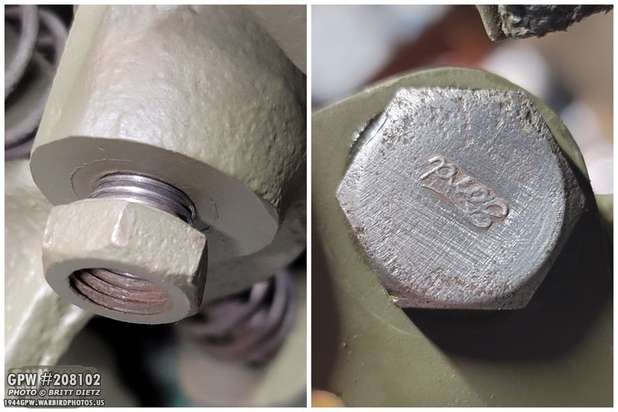
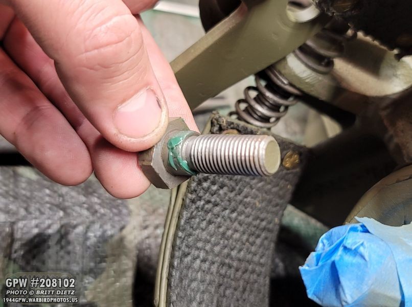
On the other side, the bolt will pop out a little and along with screwing into the e-brak bracket, you must add the small nut to hold it in place. I also wanted to point out one more time the cool full FORD logo on the bolt head!

To lock the pin in, add the special tightening nut on the bottom of the J bolt.

Almost done! Now insert the adjusting screw through the band and bracket and put the first nut on.
Add a lock washer and a second nut to that screw, and you are done with the installation!

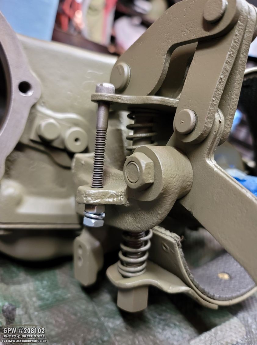
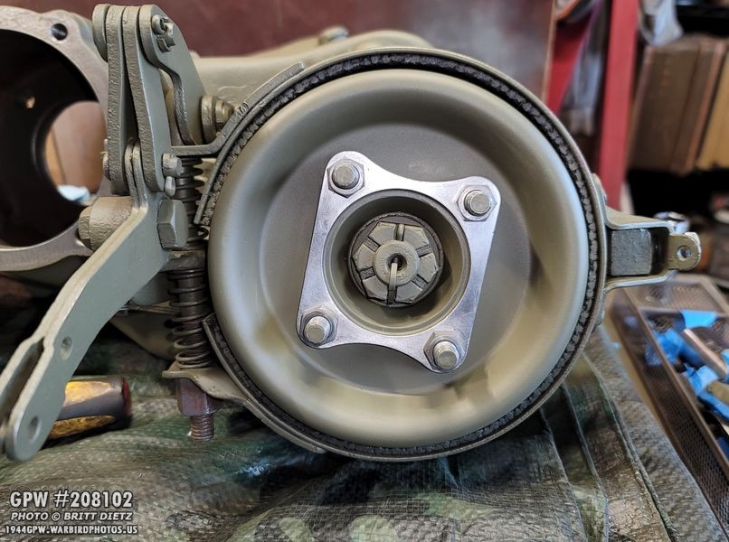
Here’s a look at the whole setup. Now, we’ll adjust it later, as we need to install the drum first!
Roger Smith gave me a neat idea to weld on the bolts to the drum, as getting wrench into the small narrow area to hold the bolt heads when installing the drive shafts is a pain. I liked the idea, and decided to do it myself. So I took the wire wheel and removed the paint around the holes. I installed the companion flange and put the bolts through to hold the bolts in place and keep them straight.
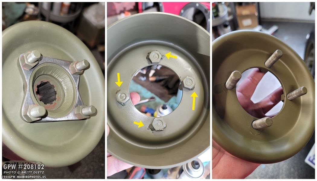
I put the nuts on the bolts so that should keep them from moving and straight as they need to be. I then added some small welds on the left and right of each bolt head. Once they were cool, I painted the heads and removed the companion flange. Those bolts will stay in place and be much easier to get the drive shaft on and off!

A few days later, a new companion flange arrived from Ron Fitzpatrick Jeep Parts. This one included the dust shield, which mine was missing, so another bonus!

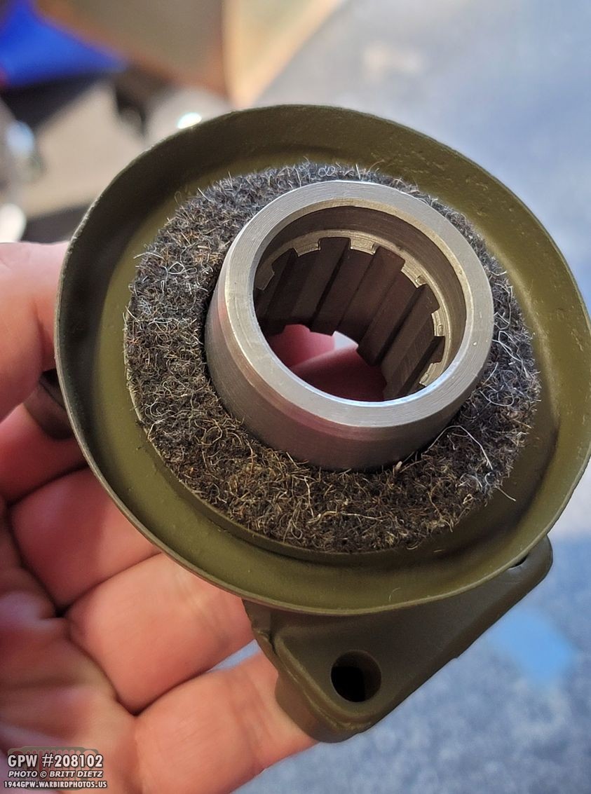
Looking at the companion flange, I noticed that there was some heavy scoring on the teeth inside the teeth. Enough to make me feel I should get a new one. It made it tough to get the companion flange on the shaft, so I decided to get a new one.

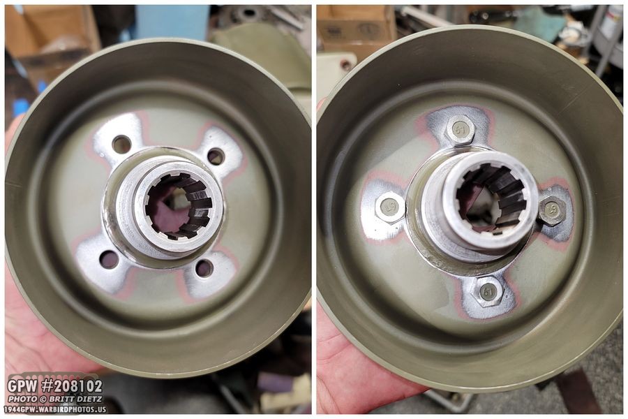
Here’s the new companion flange on the drum.

Before install, I added the felt seal to the shaft on the companion flange.

The companion flange was a source of major oil leaks last time, so I wanted to try and make sure everything was nice and sealed. It should be with new gaskets, oil seals, felt seals, etc… but I went the extra mile and added a very thin bit of RTV to the end teeth on the companion flange.

I then went ahead and pressed on the companion flange and drum onto the shaft.

Next up is the washer, which I coated with RTV as well on one side. This will help seal it further.

After putting on the washer, I went ahead and put on the castle nut and got it tight with the impact gun to the point the cotter pin hole in the shaft lined up.
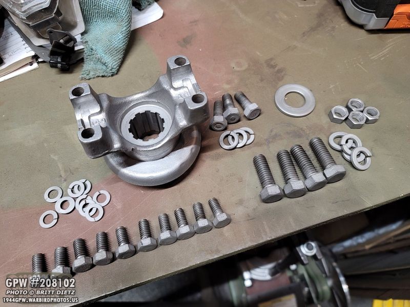
On the other side of the transfer case, I needed to install the yoke. Here’s the yoke after sandblasting and cleaning (along with some bolts).

After priming and painting, the yoke is ready!
I added the felt seal to the shaft on the yoke.

Then pressed on the yoke…

Put RTV on the washer, installed the washer, put on a new castle nut (the old one was well worn out), tightened it, and added a cotter pin.

I then painted the yoke.
And carefully painted the companion flange and drum (masking off the part of the flange that meets the flange on the drive shaft, and masking off the band). All done!
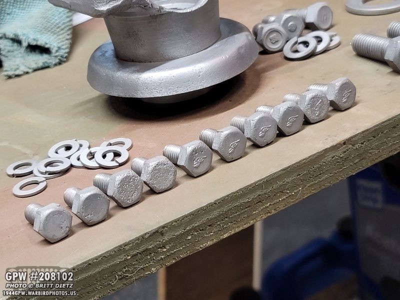
Now I needed to add the bolts to the transfer case oil pan. Here’s the bolts after sandblasting. Most of them are original F-stamped ones, but four appear to have been replaced at some point.

Last week, I put the gasket on with RTV and installed the oil pan, but I used modern bolts to seal it up and let it dry as I sandblasted the original bolts. Now that they are ready, I removed the modern bolts one at a time and replaced them with the F stamped bolts with Permatex thread sealer.

Doing this one by one will keep the oil pan tight and not break any seals from the RTV and paint.

I added my custom F stamps to the other four non-F-Stamped bolts. Once all of the bolts were installed with thread sealer, I painted the oil pan again so everything is OD Green.

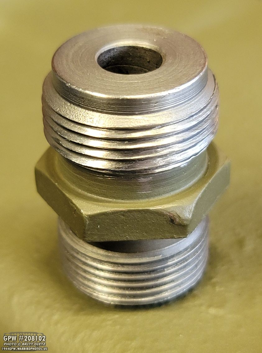
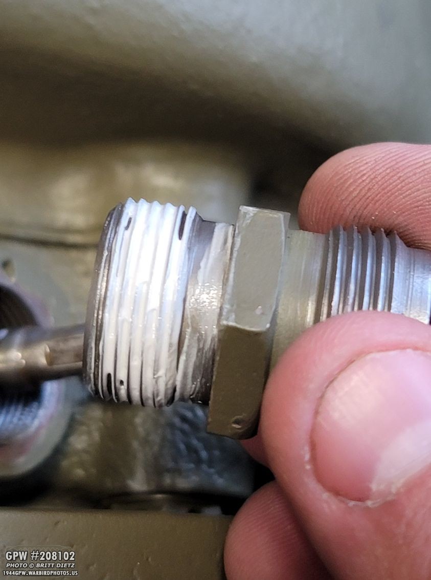
An issue I’ve had with the speedometer drive gear sleeve is some crushed threads. Not sure when it happened, before I owned the Jeep. The speedometer cable will still screw into this, but it never screwed in all the way.

My friend Tom Read suggested I used a small file to recut the threads, since I couldn’t find any die that large.
That little file worked perfectly, and it doesn’t even look like the threads were crushed! Woohoo!
I added some thread sealer to the threads going into the transfer case…

And screwed it down tight. Glad that issue is fixed! The speedometer cable should easily screw all the way on for once.

Now to adjust the emergency brake! I used the TM manual to do this. It’s pretty simple, but takes a lot of back and forth. There are three parts to adjust the brakes…
1) the side anchor screw. This pushes the band to the left, making the left side closer to the drum.
2) The J hook adjusting nut, which will pull the bottom of the band up to the drum.
3) The adjusting screw, which will keep the top of the band compressed to a certain spot.

First, tighten the side anchor screw until you can just enter a feeler gauge of .005.

Now, screw in the J Hook nut until the bottom of the band is tight against the bottom of the drum.


Now, tighten the nut on the adjusting screw until the top of the band just barely touches the top of the drum.
Go back down to the J Hook adjusting nut, and unscrew it two full turns. That should give you an aligned e-brake!

You can check to make sure you have enough clearance using feeler gauges. In my case, the band wasn’t perfectly round, so I had to do further adjusting with the J Hook nut and the adjusting screw to get it to not drag on the band.

Once you have it locked into place, used the safety wire to lock the side anchor screw from turning. That’s it, you’re done!

Two weeks ago, I talked about how I needed a new second gear, as mine had worn out. I finally got a new one from eBay. Here’s a look at the original (left) and the new (right).
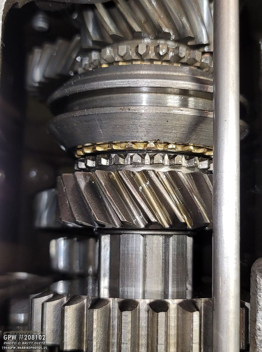
Installed, it’s a much better fit with almost no gap between the gear and the output shaft shoulder. No need for those shims!
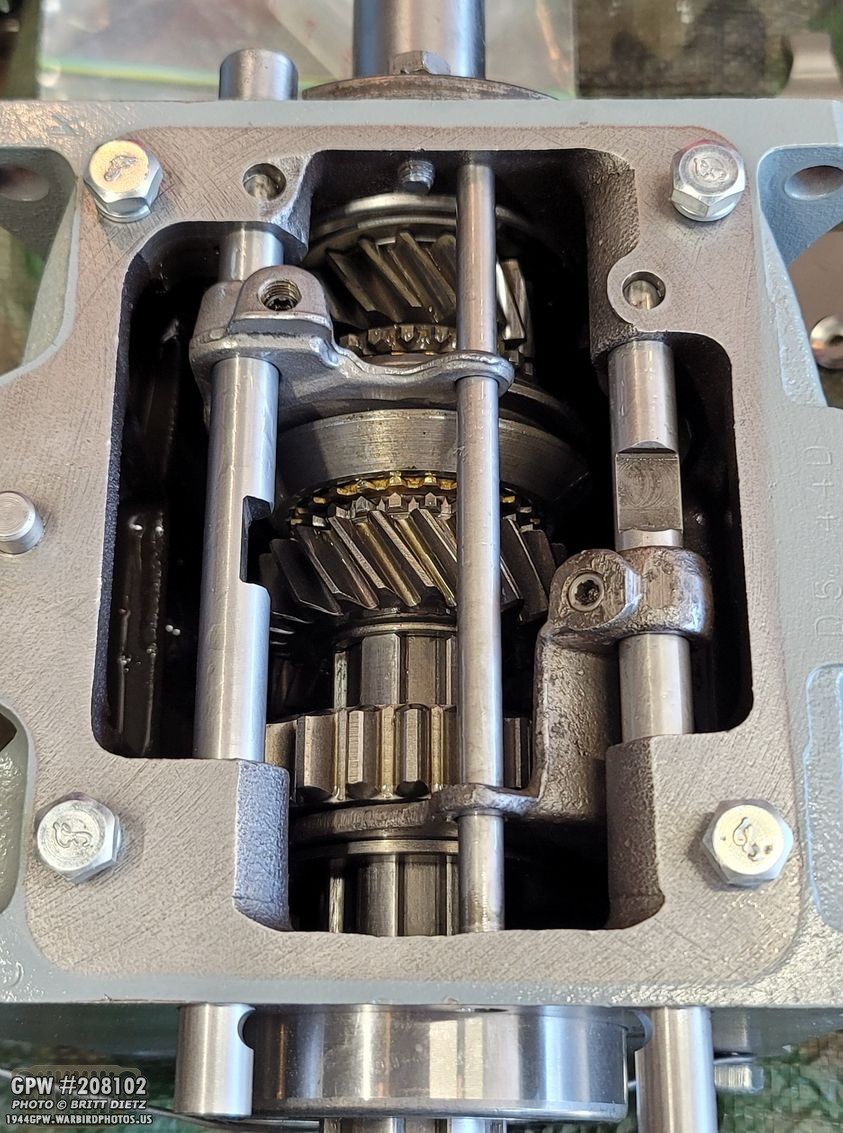
And now that the gear is in, I could finalize the installation of the shaft rods, shift forks, and the fork guide.

One thing to note, when I was going to install the shift rod, on the left side I went to put the poppet ball in and forgot I hadn’t put the spring in first. Oops! The ball fell into the spring shaft, and I couldn’t get it out. I started to get rather afraid I’d be in big trouble, as I couldn’t get it out with a magnet, using a shop vac to suck it up, etc. Thankfully, Roger Smith told me how I can take a piece of spare safety wire, and stick it up underneath the spring shaft. There’s a small hole under there for oil to get in to lubricate the spring and poppet ball. Bending the wire into a V shape, I was able to push the ball out of the shaft! WHEW!

Now the T-84 Transmission joins the D-18 Transfer Case being all finished and ready for reinstall!
Two weeks ago, I mentioned how my T-84 cover has worn down where the shifter can pivots when shifting between gears. This can cause the shifter to jump gears (which it has)

I gave it to my friend Tom Read who did some incredible work on it! The following are his photos from when he worked on it. First, here’s a look before he started.
He then cut out a large slot making a nice clean cut.

He then brazed the slot with brass (top photo) and carefully made sure the brazing doesn’t interfere with the threads for screwing the cap on. He then cut a new groove out for the shifter cane pin to pivot in.
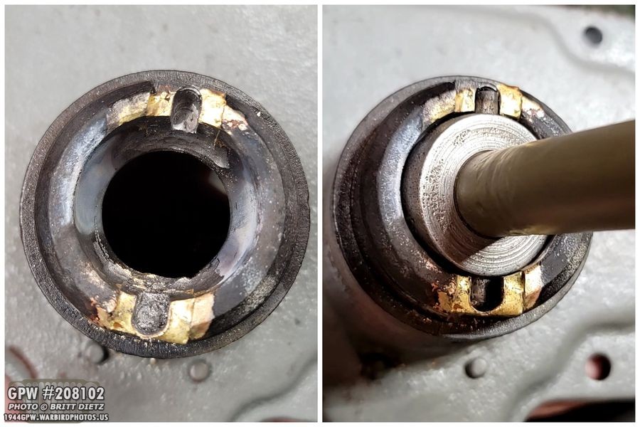
Here’s a look at the finished repair. That shifter cane fits like a glove now, nice and snug in the pin groove! Great work done, thanks Tom!

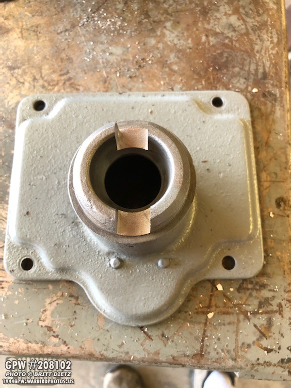
Once I got the cover back, I went to work sanding the paint so I could repaint the whole cover. Here it is with the cap screwed on.

And after a nice coat of VHT Ford Engine Gray.

Knowing that I’ll be putting the transmission and transfer case back in the Jeep, I went to work prepping the bell housing and doing any small work under the jeep in prep. I carefully sanded the mating side of the bell housing to make sure there wasn’t areas of raised paint. I originally thought of just making it all metal, but that would create a lot of paint dust.

I then touched up the paint on the bell housing everywhere else and put the cover plate back on.

Once thing that’s bothered me is the darn cheaply installed capture nuts on the body tub for the transmission cover plate. Those cage nuts have super thin metal, so the cage walls will bend out making it so the nut can freely spin. UGH. So I had enough, I sanded the area around the three bad capture nuts and welded the cages down. I also tapped the threads. MUCH better, I shouldn’t have to fit with those bolts going in anymore! I then painted it all OD Green.
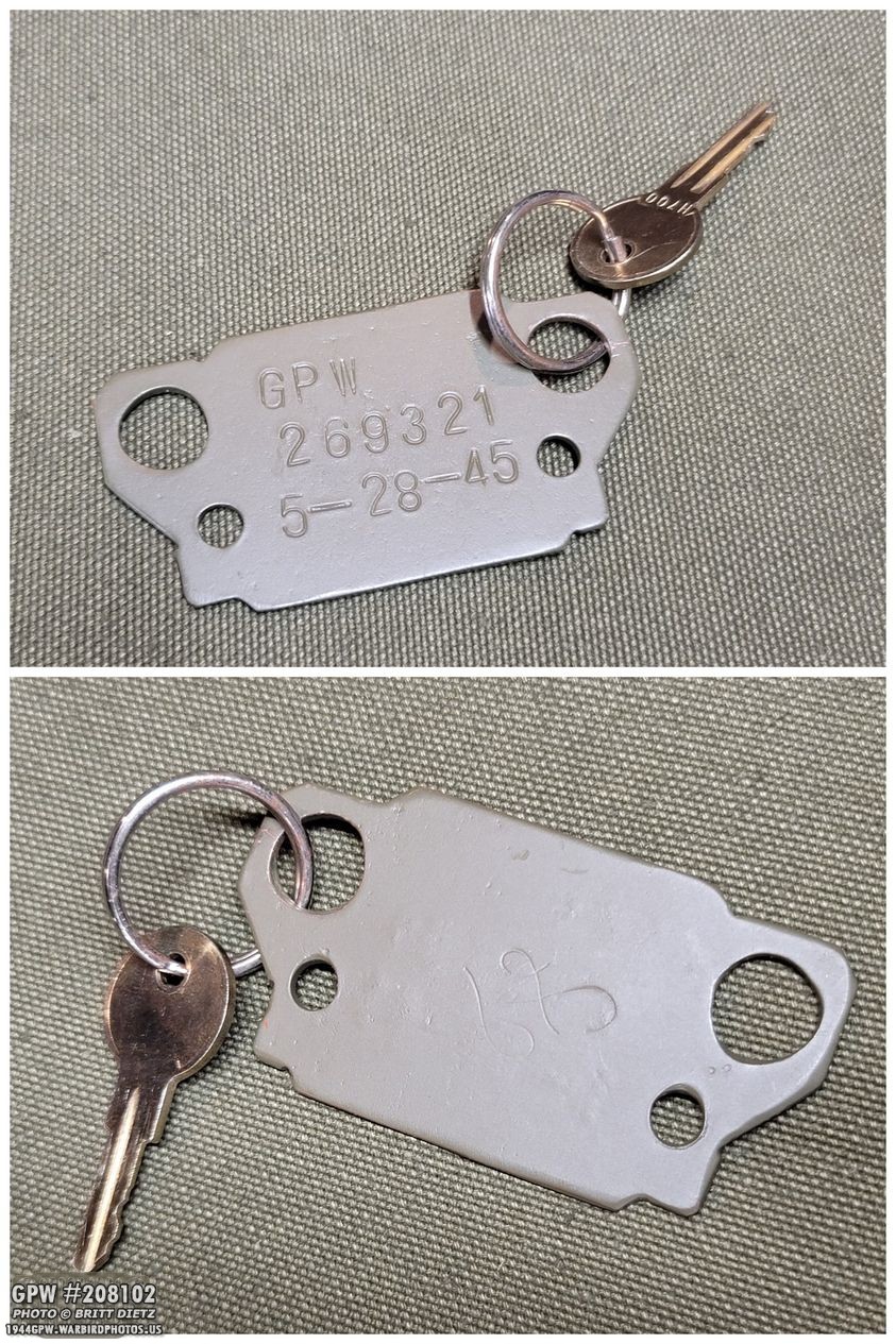
The last few weeks I’ve got some fun goodies in the mail. This is a cool keychain I got from eBay with a laser-cut grill made from a GPW part off a 1945 Jeep. The part was trashed, but the seller wanted to save the F stamp, so he made it into a keychain. I put one of my spare H700 keys on it.

As promised, Patrick from Portrayal Press sent me the ‘uber Jeep’ complete manual with the lay flat binding. I had ordered that a few weeks ago, but he was out, so he sent me (free) the non-lay flat version in the meantime. I’ve actually used it during the transfer case rebuild! I’m super glad to have the lay flat version (bottom photo), as it… well, lays flat! Anyone who’s used any Jeep manual/book knows the struggle trying to keep it open while you’re working! You can order either version here: https://www.portrayalpress.com/WW2-Jeep-Complete-p/ww2-mjc.htm

I also traded some Fire Extinguisher decals with Farrell Fox for his amazing GPW spare parts kit and tool bag from his Canvas Division Page! He does incredible work, the craftsmanship is top notch on all the items that came with the kit. I will be using all of these items on my GPW. I even plan on filling out the reproduction MWO form with major restoration milestones with the Jeep to keep as a record! I highly recommend you check out his group and all the cool things he offers, he does incredible canvas work!

So, look for a full tutorial and write up next week on mating the T-84 transmission to the D-18 transfer case, then reinstalling it all back in the Jeep. It’s been a long process for sure!

And that’s it for this week! There’s still lots to come with the Jeep, and some other fun projects in the works that I hope to complete and share soon!
Till next week…