 T-84 REBUILD!
Finally, starting the other half of the transmission/transfer case restoration and rebuilds with the T-84 complete rebuild! From an empty case to a nearly ready to install transmission, the entire process is documented. Once you get the hand of how it all fits together, it’s actually quite simple! After the build, I also attach the crossmember support bracket. Finally, a new SOS Fire Guard decal for my Fire Extinguisher!

With each week, I get closer to being able to take the Jeep back out on a drive again! Slowly but surely! This week’s update is very late as I had one heck of a busy few days. But better late than never right?

In the last three weeks, I’ve removed the transmission from the Jeep, separated the T-84 transmission from the transfer case, completely disassembled the two, cleaned everything up and replaced any items worn out… both cases have been completely cleaned and repainted.

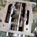
Now it’s time to start the rebuild! First up, the T-84 transmission. In last week’s update, I chronicled how the T-84 transmission works, which gears are which, how it shifts, etc. To begin I wanted to point out that all bushings and bearings have been replaced. I replaced the worn-out reverse gear bushing (shown here) with a new one. This is good practice, as often those might be the only things that need replacement. So the precursor to the rebuild is simple: replace all bearings and bushings!

With the new bushing installed, I placed the reverse gear in its little back corner spot. It should just slide down into position. Make sure you put the longer flange end side towards the front (input) side of the T-84 case.

Once there, you can insert the small reverse gear shaft into the rear of the T-84 case. You might have to raise up the reverse gear by hand as you insert the shaft so it pushes through without catching. Make sure you point the slot at the end of the shaft towards where the other shaft will go. This will be important later.

Time now for the clustergear! Same as before, the clustergear will need two bushings, one on each side of the gear. In between them will be a spacer bushing, which is free-floating, so it will NOT be snug inside the clustergear. The outer two bushings on either side, however, should be snug.

Now for the thrust washers. This is another heavy wear item and should be replaced in both the T-84 and the transfer case. For the front side of the case, the clustergear thrust washer (shown) goes onto the lower flange with the notched area on the washer placed into the slot on the flange as shown. I put a very very thin little bit of grease on the washer to hold it in place, otherwise it’ll just fall off down to the bottom of the case. This little bit of grease shouldn’t be an issue with the oil.

On the rear of the case, there are two washers. This is the first one, which a little hole cut into it. That is important for alignment. Again, put some grease on it to hold it in place.

The hole will align with a small pin on the rear flange of the case. Make sure you put the washer so the pin goes into the hole.

And then, on top of that washer is a thrust washer, nop notches on this so it will want to fall to the bottom of the case unless you put some way to hold it up.

**NOTE – At this point, you will want to make sure that you have the input shaft ready to go. Skip ahead a few photos and make sure you are ready with that, then come back here. Once the clustergear is installed, you CANNOT get the input shaft in as it locks with the teeth on the clustergear. The next set of photos I’ve done without the input shaft just to show for clarity on how the clustergear is installed. **
With all three washers in place, carefully take your clustergear and put it down into the case. You will probably knock off those washers a few times before you get it right. Once you have the clustergear in place, you might find the washers have moved slightly blocking the shaft from going through. I used a larger sized punch to go through the shaft hole and push up the washers out of the way. Then, lift up the clustergear slightly until the shaft holes align (it will want to fall to the bottom) and insert your clustergear shaft.

Before you hammer it all the way in, it’s a good time to make sure you have the slot on the end of this shaft also pointed at the other reverse gear shaft we just put in. Reason being, you need to add a lock connector plate which will hold the two shafts from being pushed in too far. It helps to try and make sure both shafts are point the right way as you start putting the shafts in.

Once the shaft is through and the lock is secured with both shafts all the way in, you’re done with the first part of the rebuild! Take some time to spin the clustergear and make sure it’s snug… it should be able to freely spin, but there should be no up/down left/right wobble to it at all. Same with the reverse gear. If it does, you either have a worn gear or a worn shaft.

Now for the input shaft, which you should have skipped to this before you put in the clustergear I hope! For this you need to go ahead and install the bearing on it. I used the new sealed bearing from Joes Motor Pool (via Ron Fitzpatrick Jeep Parts). I used my bearing puller to actually press it on. Works great for that!

To finish that off, you need to install a snap ring that will hold the bearing in place.

Flip around the input shaft, on the inside you will need to place the 13 roller bearings inside. They will be tight and hard to get in there. It helps to use a large punch to help force them in. I used needle-nosed pliers to place them inside, and used grease to hold them in place (that’s important, as they will want to pop out and go everywhere!). I then used the front of the output shaft which will go in here and ride on those bearings, to help snap them all into place. I rotated the output shaft a few times, which will force the bearings to find their place and friction themselves together. Some people remove the snap ring (which you can barely see in the front), but I didn’t find it necessary at all.

With that done, you can place the input shaft into the front of the T-84 case like so. The large snap ring on the bearing (if you buy new bearings, this bearing will come with one already installed) holds the input shaft from going in too far into the case. Again, this MUST BE DONE as you are installing the clustergear.

Here’s a look at the front. The darker outer ring is the snap ring on the bearing holding it from going in further. I then added the felt oil seal onto the shaft. You don’t want to put the front input shaft cover on yet, as when inserting the output shaft, you will need to move the input shaft out. Yes, even though it’s locked in with the clustergear, you can still slightly pull the input shaft out about 2-4 inches.

Now for the input shaft. First, you need to install the bearing. Again, I have a new Joes Motor Pool sealed bearing (blue arrow). The order goes bearing on first, then an oil cup (green), then the washer (red). Finally, you will have a snap ring to hold it in place (yellow).

Here’s a look at the completed assembly… snap ring, washer, oil cup, bearing, then the other oil cup.

Now is the time to put it partially in the T-84 case from the rear. Everything else you will do at this point will be done this way. It’s tricky, but you have to have it in there for this to work. Much like the clustergear, I’m going to show the next few steps while the output shaft is not in the case for ease of photographing.

I bought new blocking rings as my originals were pretty worn out (bottom). They are not expensive, and a good idea to replace them.

I also found that my first gear has some major gulling inside the teeth, so I go a new one of those as well (top is old, bottom is new).

(reminder, do these following steps while the output shaft is IN the case), put the first gear on first with the flange slot for the shifter fork pointed towards the rear bearing. This gear will slide back and forth, so it won’t snap into place.

To help with the next steps, a lot of items I pre-oiled with a cotton swap to help them mesh together well. Here, the second gear is getting some oil.

Second gear will push on the output shaft but stop (snapping into the non-teeth area) when it contacts the shoulder. You should feel it relatively snug against that shoulder on that smooth area of the output shaft. It should spin freely, however. Make sure the smaller ring of teeth on the second gear is facing forward.

Now, add the first blocking ring with the notched side facing forward.

Before you add the synchronizer assembly, you need to get the ‘dogs’ are in place. On the main synchronizer gear, you’ll see three spots where it appears to be missing teeth. That’s where these small ‘dog’ plates go. Another item it’s really good to replace since mine were new, they actually held themselves in the slots. There are three total, so load them in there now.

Here you can see all three of the ‘dog’ plates meshed in with the gear.

To hold them in place, you will need to then install snap rings on BOTH SIDES of the gear, like so. This will keep the dogs in place. I found putting one of the curved ends of the snap ring into one of the dogs the best way to do it on either side.

You can then carefully slip the synchronizer cage onto the gear. It will probably not want to go on with those new dogs in place, and you might find they pop out, so this could take a few tries. Here’s how both sides look once I got them all together. The snap rings will hold the dogs from coming out pushing them against the outer cage. The purpose of the dogs are to help snap and stop the travel from second gear, neutral, and third gear.

Make sure you have the inner synchronizer gear with the longer inner flange on the same side as the ring (red arrow) on the cage. This will be facing foward towards the front of the T-84 case.

To put the synchronizer on the output shaft, you might need to turn that blocking ring already on there so that the three notches line up with where the dog plates are. Once it’s on, install the snap ring which will hold the inner gear in place, allowing only the cage to move forward and back.

Here it is all installed. Again, this is a bit tricky to do while the output shaft is in the T-84, so these were all shot for example only outside of the case.

And here’s how it looks from above. Notice how there’s a gap between second gear and the blocking ring? That’s good! As the blocking ring is pushed towards second gear when shifting to second, it will tighten with second gear aligning the teeth so the cage can travel over the blocking ring teeth and lock with those small teeth on second gear. If there was no space between them, they’d always be locked together (IE always be in second gear).

You’re all done with the output shaft except to add the last blocking ring as you insert the end into the input shaft where you installed all those roller bearings (shown here).

With the input shaft moved out a bit, and pulling the output shaft back, you can just barely get the front end of the output shaft into the back of the input shaft as shown. Note the last blocking ring that’s inside the synchronizer. The three notches, this time, are facing backwards.

When all is done, this is how it should look once you push in the output shaft till the bearing contacts the back of the housing, and the front input shaft is pushed in so the bearing snap ring stops it from going further. Note the same distance of space between the blocking ring (red arrow) and the input shaft gear, which is actually third gear (green arrow). It’s the same gap as second gear and its blocking ring.

To hold the input shaft in place, you can go ahead and put on the front cover. If this is being done right before insall back in the Jeep, put the paper gasket on and be sure to use some RTV gasket maker on the side of the paper gasket going to the front of the T-84 case. I’m not there yet, so I just have it on here.

Your gears are now all installed and done! But, we need to check for any play and if you might need to add any shims to the output shaft (they go between the rear bearing and the oil cup… so hopefully you don’t have to take this all apart again to add shims…)

The easiest way to do that is to put the large rear gear on with the special castle nut, hold the rear bearing forward so it’s pushed against the back of the T-84 case, and pull on that large gear. If the shaft moves in and out, you need some shims. If not (like mine), then you’re good to go! Since I had pretty much no play, I didn’t bother using a dial indicator to check it.

To test how well the synchronizer cage moves from second to third gear, I used a halloween dollar store syringe (works perfect) to cover the gears, blocking rings, etc with oil. It’s not time to fill the case with oil, so this will help test things. You can do it dry, but it’s going to grind metal and be a lot more difficult.

It was at this point I noticed a pretty significant gap between my second gear and the shoulder it should be against… in fact, it was .026! Yikes. It should be around .003ish if anything. So I went to the computer to see what I could do…

I found one seller selling these special shims (no one else sells them) for just my issue. I’m not going to name the seller or where I got it as I don’t want to give them any more business. It took them nearly a week to mail these and they wouldn’t reply to any of my messages.

Best I can tell, the shims go on between second gear and the blocking ring (again, a guess as the seller would not reply to my questions, and the shims came without any explanations).

This actually worked, eliminating the gap between second gear and the shoulder. Putting all three shims in was too much, it locked the blocking rings with second gear and third, and the shafts wouldn’t turn. Taking out the two thinner shims, the last thicker shim was perfect. That being said, after talking with Ron at Ron Fitzpatrick Jeep Parts and my friend Tom Read, I decided to go ahead and just replace the second gear. The teeth are rounded out just enough that, while they would work fine, it’s possible a few years down the road it’ll start slipping gear when in second. So I decided it was just a better investment to get a new one. That should arrive next week (I hope) so my hope is I won’t need those shims at all with the new one.

Now on to the shift forks! Here are the two forks when I took them out of the T-84. The second/third fork (on the left) I had to drill out as the inside screw was stripped, this meant that I needed a new fork. The first/reverse (right) fork was actually in decent shape, so I decided to keep that.

After an issue with the post office losing my first package, ArmyJeepParts sent me a replacement order with a rebuilt fork, a new screw, a replacement second/third shifter shaft, and a NOS shift plate.

To install the shifter forks and shafts, first you need to put in the poppet springs and balls. These are what stop the shaft when shifting between gears. There are notches in the shafts that the ball will pop into, under pressure from the spring underneath it. This will stop the shifter from moving again without more force. Here are the two spots to put those items.

The poppet spring just drops right in each hole.

Here’s the spring down the hole in its carved-out area.

Now you can drop the poppet balls down on top of the spring. Be careful, they go all over the place and can easily fall down into the case, which is annoying to fish them out.

With the poppet balls in, place the forks on their slots as shown. This photo shows the orientation they will need to be.

I’d like to point out the shafts I got (one from my ArmyJeepParts replacement order, and one from Ron Fitzpatrick Jeep Parts, who sent me one for free with another order I’d made!) both have F stamps! I believe these are repro rather than NOS, but that was an unexpected fun detail.

And here’s the one from Ron Fitzpatrick Jeep Parts (the first/reverse shaft) with the F stamp.

There are two shafts and one guide for the shifter forks. The left is the second/reverse shaft, the right is the first/reverse shaft. The middle is the fork guide pin which will help keep the forks oriented the same. NOTE the three notches in the two shafts, this will be important when putting them in the case in these next steps. These three items are replacements, as the originals had wear marks. It’s just better to replace these now rather than have issues later.

With the notches on the first/reverse shaft pointed straight downward, start to push in the shaft from the rear of the case. Move the shift fork so the shaft goes through that main hole. You might have the twist the shaft back and forth to get them to feed through, especially if the shafts are new but the forks are not. STOP before you reach the other side of the case, as we need to do something to the poppet ball.

If you push the shaft all the way in, it’ll knock off the poppet ball in top of the spring, and you’ll have to retrieve it. In order to get the shaft to go over the ball, you need to push it down as you’re pushing in the shaft. Here I’m using a punch to push down hard on the ball so the spring compresses and it goes down into the shaft. It’s a small punch so I can get the shaft to partially start to go over the ball. Once the shaft is about to hit the punch, it’s enough on top of the ball that it’ll hold it in place. You can then move out the punch as you push the shaft all the way in and you’ll feel that ball ‘lock’ into the first notch on the shaft.

It’s the same thing with the other fork… push the shaft in with the notches facing down, twisting if it gets stuck… put it through the large hole on the fork, stop before getting to the other side, push down the poppet ball, push in the shaft, pull out the punch when the shaft almost hits it, then push the shaft all the way until the ball pops into the first notch. NOTE – See that other notch on the shaft in the middle? That’s where the fork will go. When you insert the screw pins (next images), you need to make sure that notch (and the one on the other side) are inside the fork.

And here’s a look at the fork screw pins. Now, the original pins have a special gear looking thread on them for a special tool (right), the new replacement ones from vendors often instead changed it so you can just insert an Allen wrench and tighten it. That’s why my second/third fork was stuck and needed to be drilled out, someone had used an Allen wrench on the special gear style teeth and stripped it bare. UGH.

I found that one of my small screwdrivers perfectly fit with the teeth of that older gear style (which the name escapes me, starts with a B) teeth. NOTE – That little notch is how these tapered screws lock the fork to the shaft. That long flat notch in the shaft is for the shifter plate.

The second/third gear fork’s tapered screw was much more recessed than the otherside’s one.

As you can see, this one isn’t as recessed as much. But both are locked to the shaft nice and tightly.

You can now insert the guide pin, which goes in through the back through the smaller holes on both forks, and into the hole in the front.

I decided to install the drain plug now, using Permatex thread sealer on the end and tightly screwing it in. I then hit it with the Ford Engine Gray like the case (which will also help seal it up).

I then realized that rather than fighting to fill it up with oil while it’s mounted under the Jeep, for the transmission I could actually fill it with oil from inside the Jeep with the main transmission cover off. That’ll be so much easier and faster! You just have to watch the oil level and stop the second it hits the bottom of the fill plug hole. So, I went ahead and installed the fill plug, again with thread sealer and painted it.

Next up, I installed the transmission mount bracket to the bottom of the T-84 case. I wasn’t sure if this bracket should be Ford Gray or OD Green. After researching it and talking with several people, the general consensus was that it’s actually OD Green, NOT painted Ford Gray. Here, I’ve added the original three F stamped bolts and the other bolt (that had no markings) with a custom F stamp.

After some paint, here are all four bolts with F stamps (and some pitting) and the F stamp on the bracket plate itself.

The T-84 is pretty much done now, but it’s a good idea to test it all. To do that, you need to hold the bearing and output shaft in place, as it will push out if you try to change gears. I used some wire going over the bearing with bolts to keep it locked in place.

One thing missing from many T-84s is the spring washer for the shift plate. You can add that now.

Then pop on the shift plate (note – this is an old photo of when I was testing things with the old hardware, thus the not-so-clean shift plate. I forgot to take a photo of everything all put together). I’ve read that the shift plate goes on TOP of the spring washer.

From there you can add the cover, shift cane, spring, cupped washer, and cap. With the wire holding the output shaft in place, you should be able to shift to the different gears and see how it all feels. Worked great for me, it was nice and snug shifting to each gear with almost no wobble. Much much better than before! After that, you can take the cover off as you will need to install it without the cover or shifter cane. I’ll go over how those are installed in a later update. But with that, you are ALL DONE with the T-84!

And, my T-84 cover needs some fixing as well. You can see in this photo that the slots have worn away quite significantly, to the point that this was probably how I shifted into second and the shifter slipped out and went into the neutral position making me stuck in second last year. So I left it with my friend Tom Read who has a process to fix this. I’ll showcase what he did once I get it back next weekend.

Moving on to one other quick project… so a few months ago I chronicled how I took a wartime era fire extinguisher and put a custom SOS Fire Guard decal on it that I made using originals (researching the original fonts, colors, spacing, materials, etc) making it from scratch. The glue I had used on the decal was starting to peel away from the paint, so I decided to try something new.

I removed the old decal (it ripped apart as I took it off), and took another one I had printed. I resized this one slightly smaller than the original one, as I’ve recently gotten an original fire extinguisher with a mostly intact original decal and was able to figure out the exact size mine needs.

I sanded and repainted the fire extinguisher, making sure to scuff up the area where the decal will sit with sandpaper (and leave some areas unpainted) for better adhesion. I used painter’s tape to mark where the decal should sit. This type of thing isn’t repositionable, so once you get it started that’s it!

One of the Hobby Lobby employees suggested I use this thin tape when I explained what I was looking for, instead of spray glue or glue dots. I figured it was worth a try. It’s not super easy to apply, but boy is it sticky! I made sure to line all four edges of the decal with it, and make several patterns of strips in the middle.

The result is that it seems to be holding MUCH better than the previous glue I was using! Time will tell for sure, but it seems to not want to flip the edges up. And, with the smaller correct decal size, it seems to be holding better as well. I’ll check back in on the decal in a month or two and see how it’s doing. But I’m happy with how it looks.

And that’s it for this week! As you can see, I’ve already made significant progress with the transfer case rebuild, but I figured only one update per rebuild, so look for that complete rebuild on Friday when I return back to the normal Friday updates. Thanks again for all the kind comments and messages from people who’ve found my posts helpful. If I can help people as they restore their Jeeps, then I’ve made all this work documenting everything worth it! Till next week…