 Quarantine work!
This week was one of the busiest weeks I’ve had in a long time during this restoration, mostly because of the current stay-at-home quarantine. The e-brake project was mostly finished, I sandblasted and finished all four brake assemblies for the new axles, and wire wheeled other items!

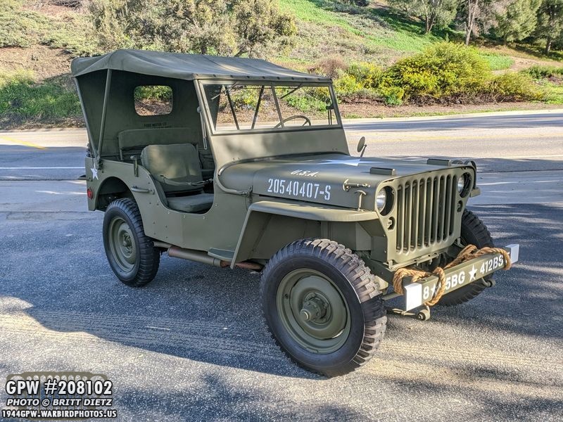
After a bit of downtime for the Jeep, she’s back up and running again! With the current California Stay at Home order, I’ve been at home all week which meant a LOT of work done on the Jeep. There’s a lot in this update so let’s get started!

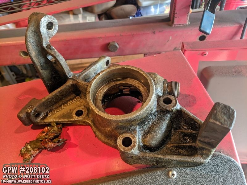
The last few updates I’ve been work on fixing the emergency brake, which is the earlier external type. The drum was damaged and the lining on the band was all but worn away. Here’s a look before I started work on replacing things.

The last thing I did in the last update was take off the e-brake housing bracket and removed the oil seal (it’s still in on this photo). The next step was to restore the housing.
After dipping it for a few hours in mu ‘bucket-o-gasoline’ to eat away the oil and grime, this is how it looked. Better to get as much as I can off before gunking up my sandblaster.

After sandblasting, nice and clean!!

Here’s all the markings I discovered on this housing bracket, including a F stamp. Possibly a date of F 42?
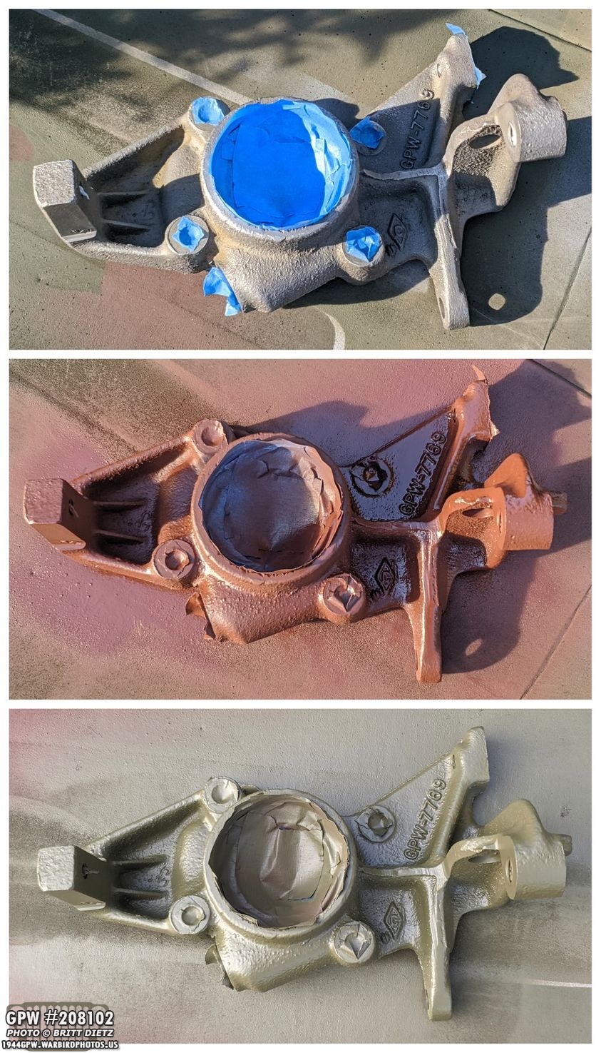
After masking off all the internal areas and bolt holes, I hit it with red oxide primer (Red Barrier II from Ron Fitzpatrick Jeep Parts) and then 33070 OD Green.

Inside the housing is this speedometer driven gear. The geared shaft that comes out of the transfer case goes through the e-brake housing, and it spins this gear which in turn spins the speedometer cable that is screwed on to the large doubled threaded bolt. On the left shows both parts, and on the right shows how they are put together.

On that speedometer driven gear it has SW 448033. Looks to be original (Stewart Warner?)
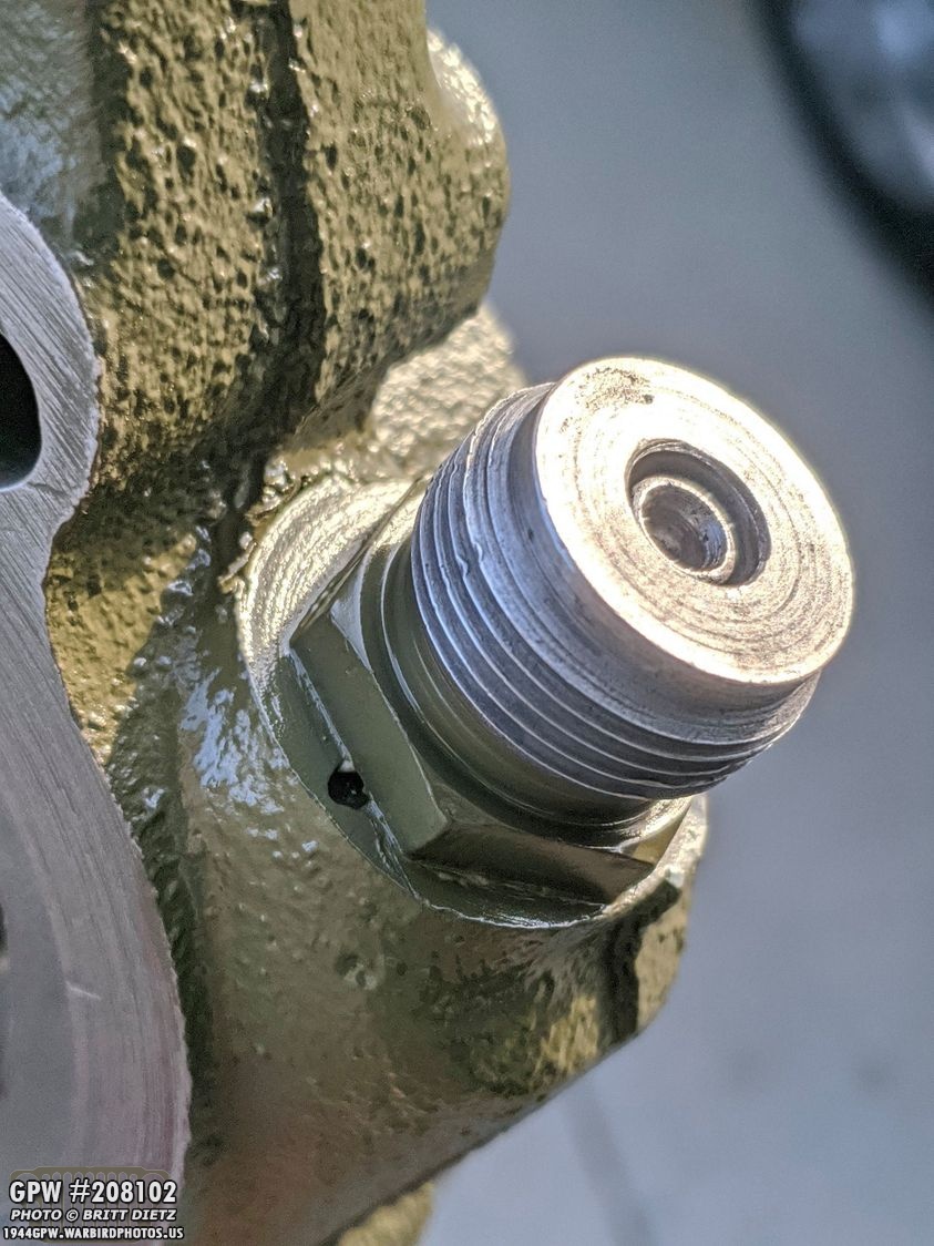
Here’s the main sleeve bolt put back on the housing with the end of the gear in the middle hole.

Here’s a look at the speedometer driven gear inside the housing all reinstalled. I made sure to put some oil on either end (along with making double sure everything was super clean) so it could spin without any issues.

With the gear reinstalled, it was time to put the new oil seal in the housing. Here I’m using a block of wood to hammer down the oil seal (which you can just see with the red color). Using the block of wood helps to make for a nice even pressure all the way flush.

Here’s a look at the housing bracket with the oil seal all nice and flush with the outside edge.

Next step was to clean, as best as I could, the mating surface on the back of the transfer case. It looks dirty, but it’s pretty clean.

On the advice of Roger, I put some RTV on the back of the housing bracket that will mate with the transfer case to help create a better oil seal. It’s a very light coat of RTV.

For the bolts, I put a tough of RTV on the copper washers and also put non-permanent thread sealant on the end of the threads just in case.

All four bolts installed and torqued on the housing plate!

The final step is to put a safety wire through all four bolts. This will help keep them from spinning loose.

Getting the drum back onto the shaft was NOT an easy task. The drum and yoke did not want to slide down the shaft, so I had to take a rubber mallet and carefully pound the drum down until the first bit of thread was showing on the shaft. I was then able to partially get the nut started, which I was then able to use my air impact gun to get the nut fully screwed on, which also pushed the drum all the way. I then put the cotter pin through the nut and painted it all.
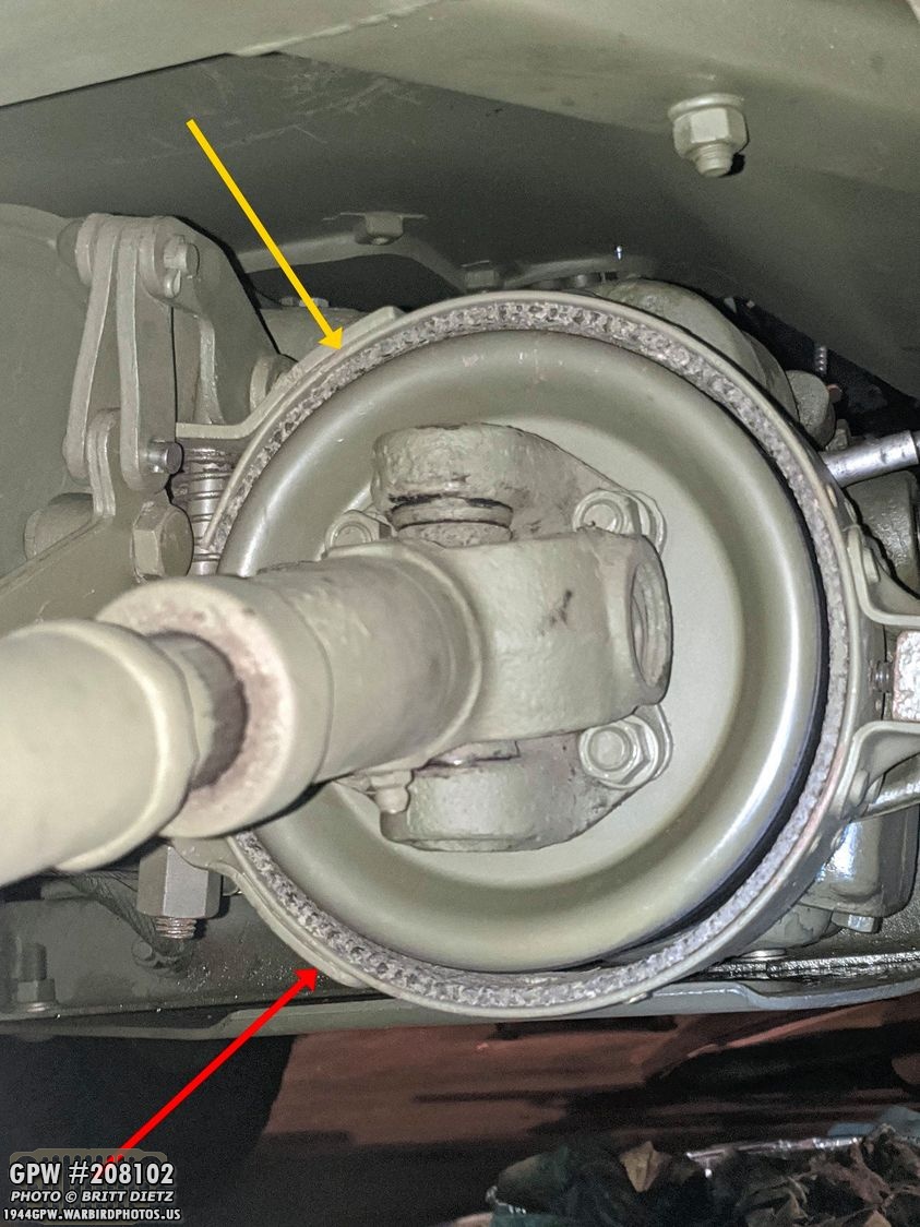
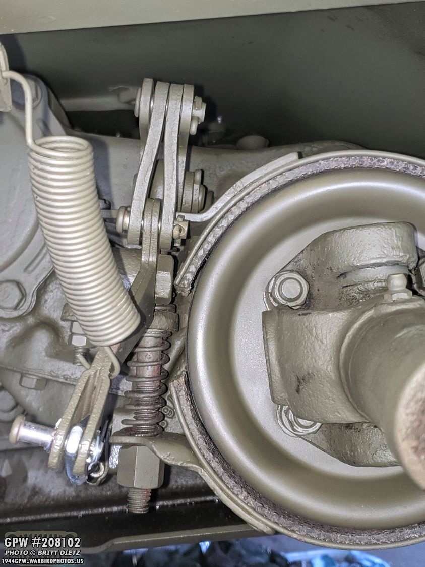
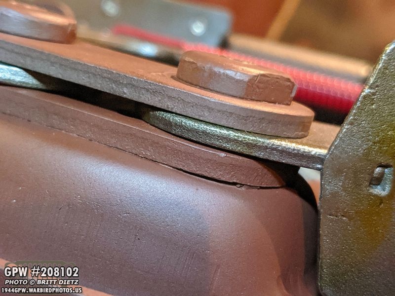
With all of that put back together, I went ahead and put together all the e-brake linkage and the outer band. That also proved to be tough as the J hook for the linkage has little to no clearance to get it in the outer band and housing bracket. After I got it all together, I started to notice an issue. No matter what I did adjusting it, the top of the band was rubbing against the drum (yellow arrow). The bottom had a large sized gap (red arrow). Uh oh. I put the propeller shaft back on to see if that made a difference, and it didn’t.

I ended up having to take the band off again. Once off and taking a look at the band, it was clear the problem was the band had gotten bent a bit out of circular shape. You can see on the bottom photo the top side was more bent inward than the bottom. So I manually bend out the band so that when I squeezed the ends together, they were more aligned.
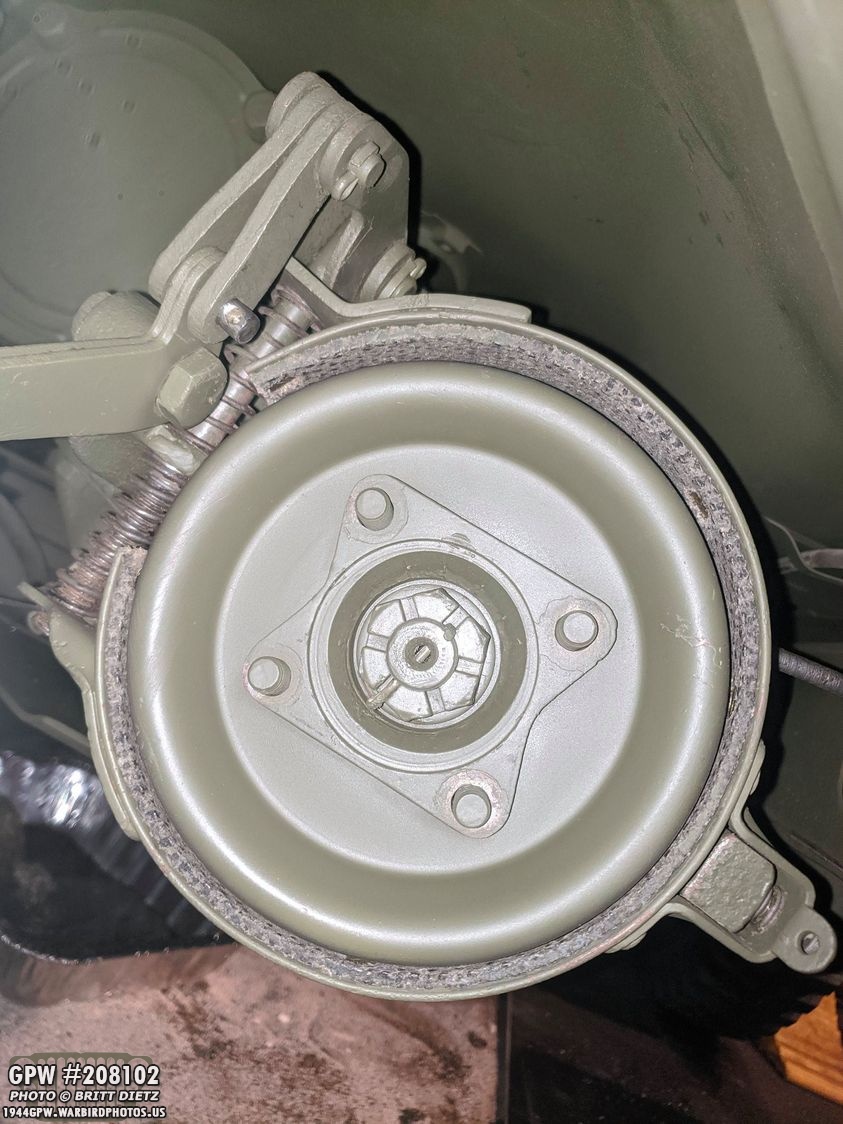
Putting it back on the drum and re-hooking up all the linkage, success! The top wasn’t riding the drum and there was clearance on all sides. The bottom still has a bit of a gap, but that should go away after more adjustment.

I reattached the propeller shaft and also adjusted the side adjustment bolt (on the right) that slightly pulls the drum away from the drum and also keeps it stable. You can also see the silver speedometer wire screwed back into the housing bracket that I worked on earlier.
With the housing bracket back on the end of the transfer case and the drum on, it was time to put oil back in the transfer case, since it came out when removing the drum and housing bracket. I had ended up unscrewing the drain plug (shown here) and let the rest drain out to replace all the oil. To replenish it, I first cleaned up the drain plug, added some thread sealant (non-permanent), and screwed it back in.

Here’s the drain plug back in the bottom of the transfer case after cleaning up the excess thread sealant. I’ll paint all of this with some OD Green.

With the drain plug back in, now to put the oil in the transfer case. I went out to Harbor Freight Tools and got a cheap gear oil hand pump.

Here’s a look at the gear oil starting to be pumped out of the gallon jug and into the side fill hole. This was not an easy process, the pump said that it fits on most gallon containers, and the Valvoline container apparently wasn’t one of those. So it took a good 10-15 minutes of pumping to get all the oil in. What an arm killer! I’m using 85W-90 gear oil.
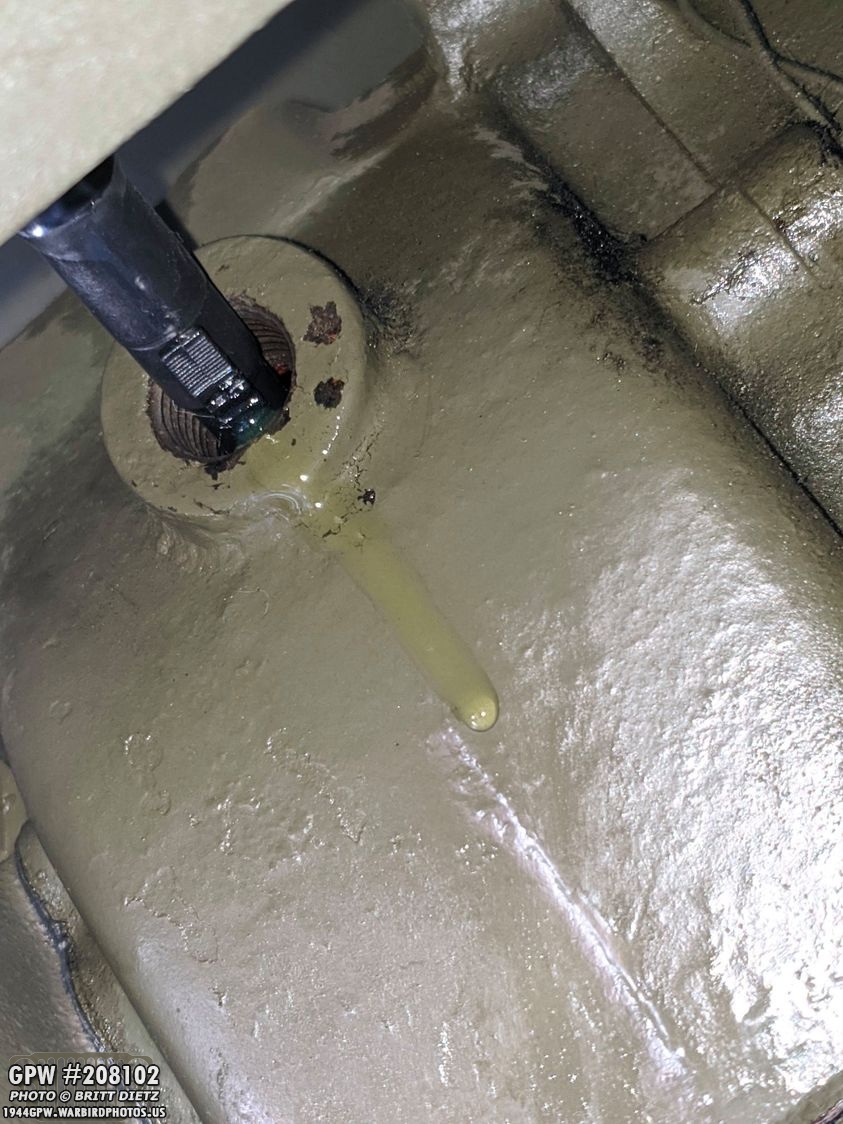
How you know you’re done is when you start to see the first drip come out of the fill hole. That means you’re done! Clean it up and replace the fill hole plug.

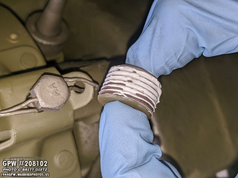
I used some thread sealant on the fill hole plug (top) as well. After it was cleaned up I sprayed both plugs with paint. These both were areas where I had slow oil leaks, now 4 days later there’s still not a drop of oil leaking even after two drives!

And here’s a sort of before and after of the emergency brake. It was a long process getting it all cleaned and replaced, but I’m happy to have it finished. I still need to adjust it further to get the right clamping to really be effective, but it’s close!
Here’s a look showing the linkage that controls the clamping of the outer band on the drum. The large nut on the large J bolt at the bottom is one of the two ways to adjust the band. I’ll cover the adjustment and how it works in a future update.

With that all done, I took the Jeep out for a test drive for the first time in about two weeks. It was nice to drive her around again! No rubbing that I could hear on the drum but the other band on the e-brake, and no oil leaking from the transfer case! So even though the e-brake still needs adjusting, it was a successful drum replacement.
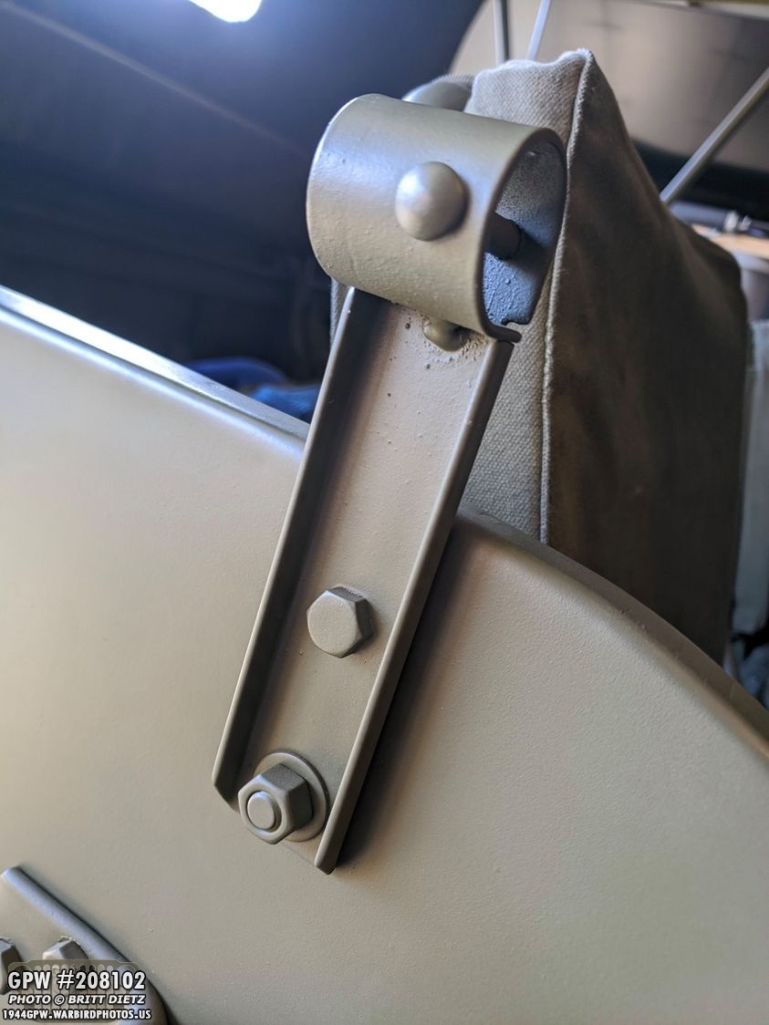
Next project was a small one, but the ongoing effort of replacing all visible bolts with F stamped bolts continues one or two bolts at a time! While my top bow brackets are not F stamped (they will be eventually!), I had two replacement F stamped bolts come in my last order from Ron Fitzpatrick Jeep Parts. The bolt on top is the one I’ll be replacing on the brackets on both sides.

After installing and painting, another F two F bolts down! For those who say ‘why is one sideways?’ Well, they were just put on during WW2 without any worry of what way the F was oriented. For those asking why one of them is oriented perfectly, that was total luck with how it aligned when tightening it.

Next up, I wanted to finish the steering arms removing the last bit of paint and rust.
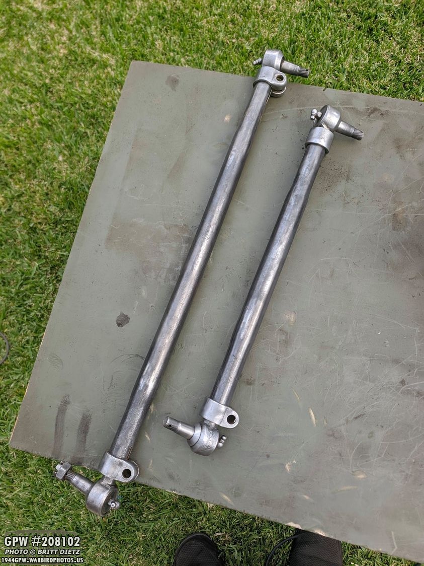
After wire wheeling they both look nice and clean! I still need to do a lot more work to get the tie rods off the end, they are on there VERY tightly with 75+ years of sitting in the steering arms. I’ve since soaked them in my bucket of fuel and then PB Blast but they still won’t budge. That will be a project for next week.

Once I get the tie rods off, I can sandblast them to get the rest of the dirt and paint.

Here’s a better look at the markings on one of the steering rods. It has a nice script FORD with U.S.A. C

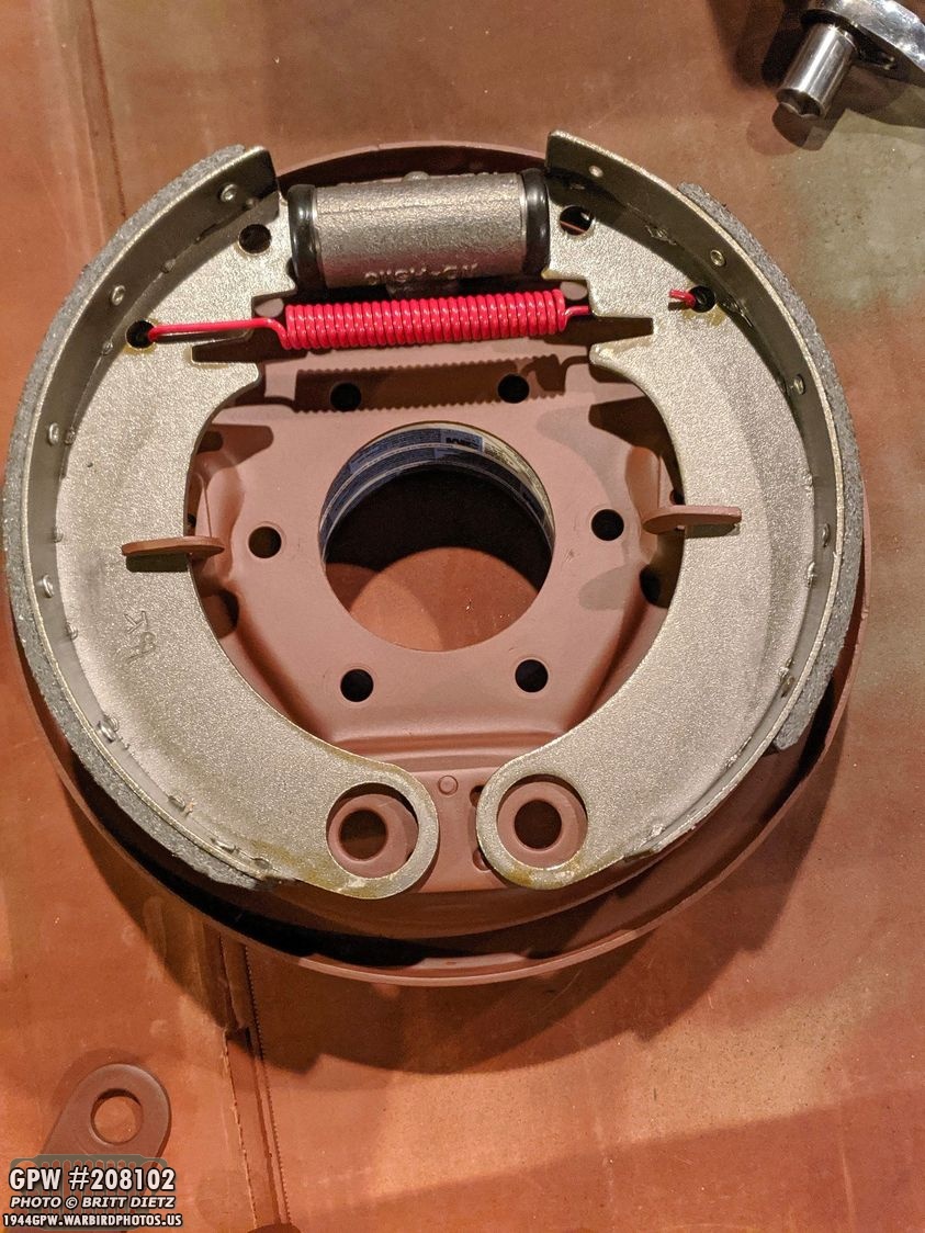
The biggest project this week was the cleaning and reassembly of the brakes on the 4 wartime GPW axles that will eventually replace the CJ axles on my Jeep. Last week I showed the first assembly put together, and this week I started on the second one. Here I’ve sandblasted clean the next brake packing plate and painted it with the Red Barrier III Red Oxide paint. The inside of the brakes were painted Red Oxide but not OD Green, so I will wait to paint the OD Green on the axles until they are put together.

The last two backing plates were pretty caked with 75 years of dirt, oil, grease, grime, etc. To help out my sandblaster and prevent clumps of debris getting into the sand, I ‘pre-cleaned’ the plates with a wire brush and dunked them in the bucket of fuel to loosen the oil that was caked on.
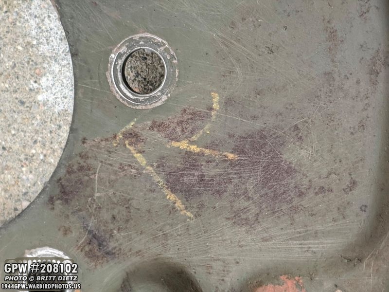
Under the dirt, I noticed what appears to be an R written with yellow something on one of the plates.

Here’s a look at the next plate after sandblasting, but before cleaning the sand.
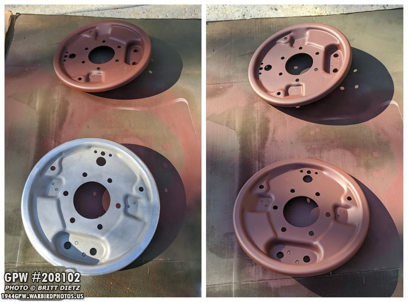
Cleaned up on the left, and then painted with Red Oxide on the right. They look brand new.

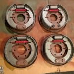
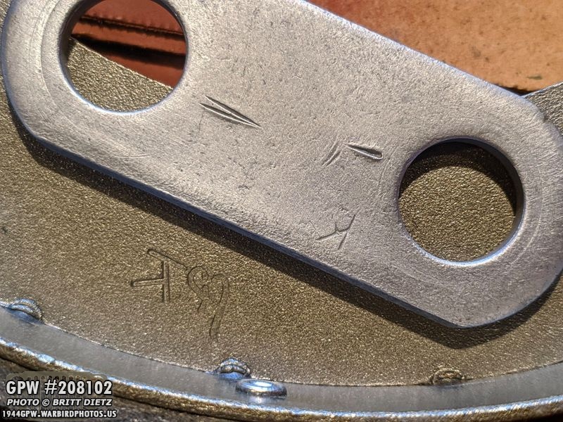
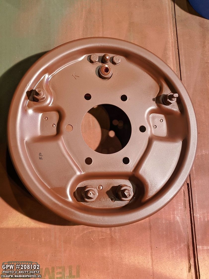
Before I go into assembling the brakes, I wanted to show the difference between brake plates. The front axle had K brake assemblies, which were Ford only form what I’ve heard. These had a K stamped somewhere near where the cylinders are bolted on (left one). The rear axle had Bendix assemblies, which have a large 4 logo and part number on the bottom left (right plate).

Another closer look at the two plates. The top is the Bendix (Ford and Willys) and the bottom the Ford.

And finally, before I begin, here’s a look at three completed assemblies with the final one before I sandblasted it.

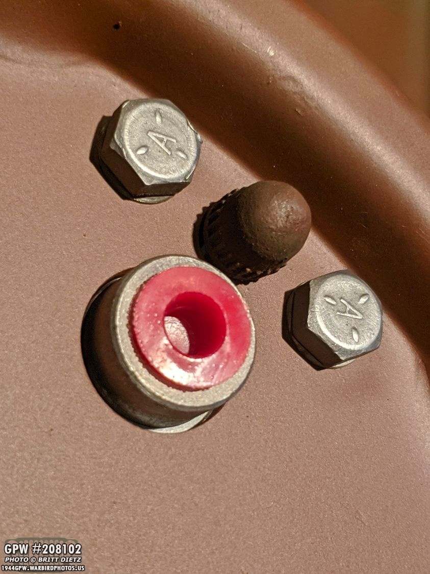
Now to begin the reassembling! Here’s a look at all the parts. The reproduction parts I got were new brake shoes, new cylinder (in the box), and a new spring. The rest of the hardware I had for all of the four brake assemblies but one, which I needed all repro items. In this photo, the bolts, nuts, washers, etc are all original.
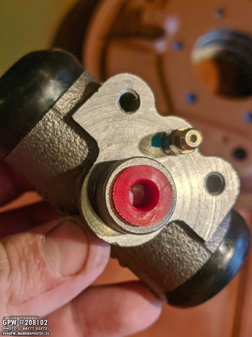
Here’s a look at the reproduction brake cylinder, one of the four that came in the brake kit from Ron Fitzpatrick Jeep Parts. They are made by Joes Motor Pool and look pretty exact to the original ones I took off. They have a cap where the steel brake line connector to protect from debris. The top gold connector is the brake bleeder valve. And the two holes are the bolt holes to bolt it to the backing plate.
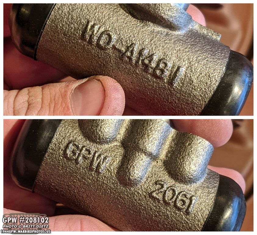
They have dual numbers on them, GPW on one side and WO on the other for Willys or GPW part numbers.

Step 1) attach the cylinder on the top of the plate.

I used the original bolts (which fit perfectly) and I tightened them down.

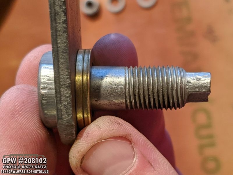
Step 2) Next, you need to install the two small brake shoe adjuster bolts on both sides, as once you get the brake shoes on they are pretty much impossible to get in there.

First, place them so the elongated side of the head is facing inward. These bolts will be adjusted to push out the brake shoes closer to the drum for proper clearance later when the drum is put back on.

I then put the lock washer and nut on the bolts from the other side. They are not torqued down but tightened enough that they won’t turn. When you go to adjust them later on, you will turn the rectangular non-thread end and then hold it in place while you tighten the nut.

Before I go on to the next step, here’s a look at the original spring vs the new spring from the kit. I thought about using the originals, but from a safety standpoint, I went with the new ones just in case.
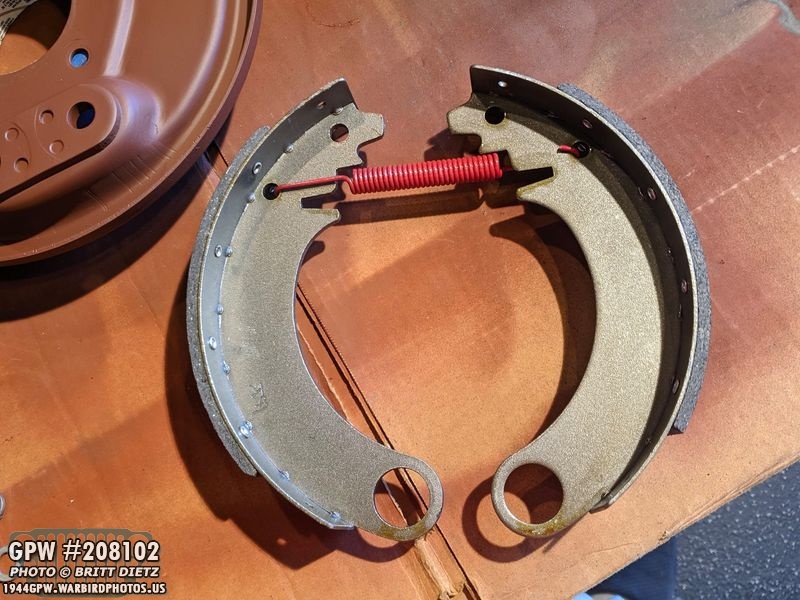
Step 3) To put the brake shoes on the plate, it’s a bit of a trick. I’m sure there are many ways to do this, but here’s what worked for me without any tools. First, put the spring in the holes shown. Note – I have two short lining brake shoes here, but there will be one long and one short.

And another shout out to Ron Fitzpatrick Jeep Parts who made sure I got F marked brake shoes! They will never been seen once enclosed with the drum, but still fun to know they are in there.

To install the brake pads on the plate, first, insert the left shoe into the cylinder (yellow) with the tab on the shoe going into the slot. Then make sure the shoes goes into the stopper (blue arrow).

Then, stretch the other tab over into the other side of the cylinder (yellow arrow) and then grab the bottom of the shoe and rotate it over until you can put the other shoes into the stopper.
Once done, it should look like this. And here you can see the left brake shoe has the longer lining, while the right side has the shorter lining. You want the shoe with the longer lining to be the shoe that will face forward on that plate. This is the rear passenger plate, so the longer lining shoe is on the left, which will face forward.

Next up is the brake shoe anchor pin plate. Here’s my original one for this plate.

And while some of the photos show it not painted, I ended up painting all the plates (left) with red oxide to protect the metal.
Also, this particular plate is stamped K, just like the backing plate and also the repro F marked brake shoes.
Step 4) To install the anchor pin plate, you need to install the large adjusting bolt with the brass anchor pin cam. Here is the bolt with the anchor pin plate and the brass cam in the order they go.

Here’s another look at the three items. The brass cam only goes one way on the bolt, you can see the inner hole on the brass cam has a point, same as the bolt.

Before installing the brass cam, I put a thin layer of grease on the outside edge.

Here both brass cams are in the brake shoes and cleaned up of excess grease.

Push the anchor bolt through with the anchor pin plate. This took a bit of time to do to get it aligned with the brass cam and also through the hole on the backing plate. I had to wiggle the brake shoe and the anchor plate back and forth before I could finally push the bolt down fully.
Here’s a look at how it should look with the bolt head, the anchor plate, the brake shoe, and the backing plate.

It helps to put the lock washer and nut on the other side as you do each bolt, or the first one can pop out as you try to get the second one in.

And here’s how the completed assembly should look! Here you can see the anchor plate and the head of the anchor bolts painted with the red oxide.
Now, the backside all the bolts, nuts, lock washers, and the back of the cylinder are all unpainted and exposed to the elements. So I used one of the rubber caps on my CJ axles that cover the brake bleeder valve to protect it from paint…
And I painted the entire backside. Again, this side will get OD Green once it’s all re-installed back on the axle and I paint the entire assembly.
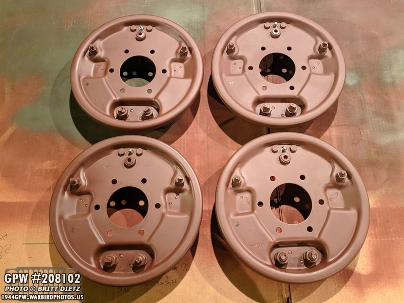
Here’s a look at all four plates finished and paint (the backside).
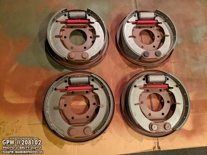
And the inside of all four. If you look at the lengths of the lining on the brake shoes, the top row is from the driver’s side (longer lining facing forward – left), and the bottom is the passenger side (longer lining facing forward – right). The top right assembly has the two reproduction bolts which came from RFJP pre-coated. And that’s it for the brakes for now!

Moving on to the drums, I started to wire wheel the first drum. It’s a bit tough to get in all the little areas with the wire wheel, so I’ll sandblast them once I get most of the paint and grime off.
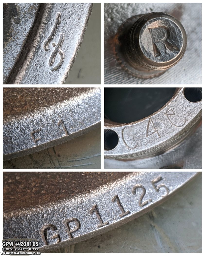
Here’s a look at the markings on this drum. There’s the Ford F stamp, all the studs have R (for right hand thread for the lug nuts), F1, C4C, and the GPW GP1125 number.

Wrapping up this post with the last few shots, I wanted to post my speedometer is up to 178 miles I’ve driven the Jeep since I first started driving the Jeep after the bulk of the restoration. Not too bad for mostly driving around the local area.
With the stary-at-home order lasting for what looks like another 2 or more weeks, I’ll be able to get a lot more done on the Jeep for the next few days. My hope is maybe, within the next 2 weeks, of being in a spot where I might be able to replace the CJ axles with the completed wartime ones. I also hope to acquire combat rims soon and looking into getting 4 firestone military NDT ties (the spare tire is already firestone).
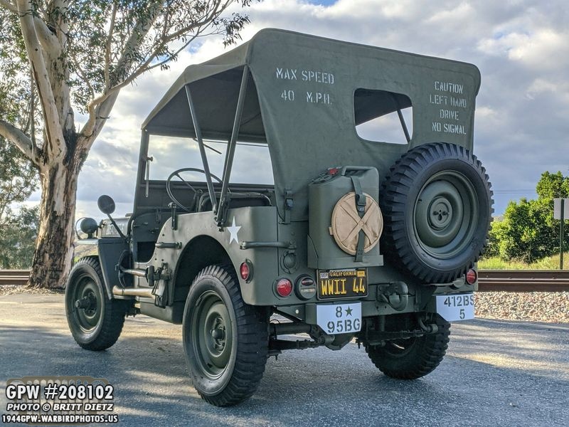
And with the rear of the Jeep, this is the end of this long update! Lots of work this week, and hopefully next week follows suit! Till next time!