 Adjusting the valves
Happy Thanksgiving to all who celebrated yesterday! This week I was able to set some time aside to adjust the valves on my engine since the starter is still out for repair. I also fixed the heat riser that was installed wrong on the engine. Plus, the stencils for the Jeep markings arrived!
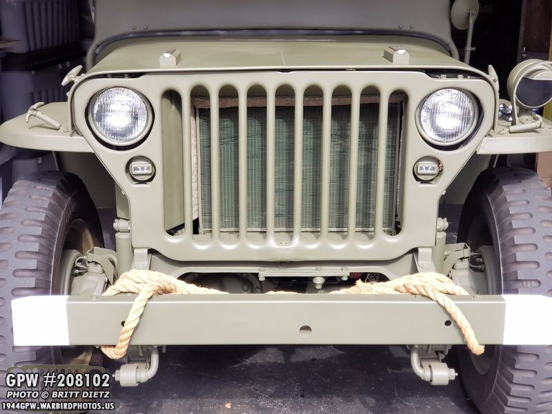
Another look at the classic grill of the Jeep. And probably one of the final shots I take of the front without any markings on the bumper!
If you read last week’s update, you saw that after removing the manifolds from the engine to do a valve adjustment, the intake manifold broke pretty significantly on one of the ears.

With a new intake manifold on the way scheduled to arrive today, I went ahead with taking apart the two manifolds.

Here’s the intake manifold removed, with the large section missing. The new one is coming from Kaiser Willys Auto Supply and should be an exact fit to replace this one. Note, you can tell it has been cracked for a bit, the right side as more debris build-up than the left.

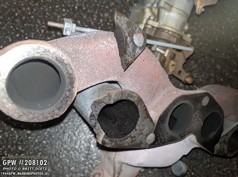
And a closer look at the ear that cracked. Many issues I’ve had with possible air leaks and other loud engine sounds could be related to this cracked section.

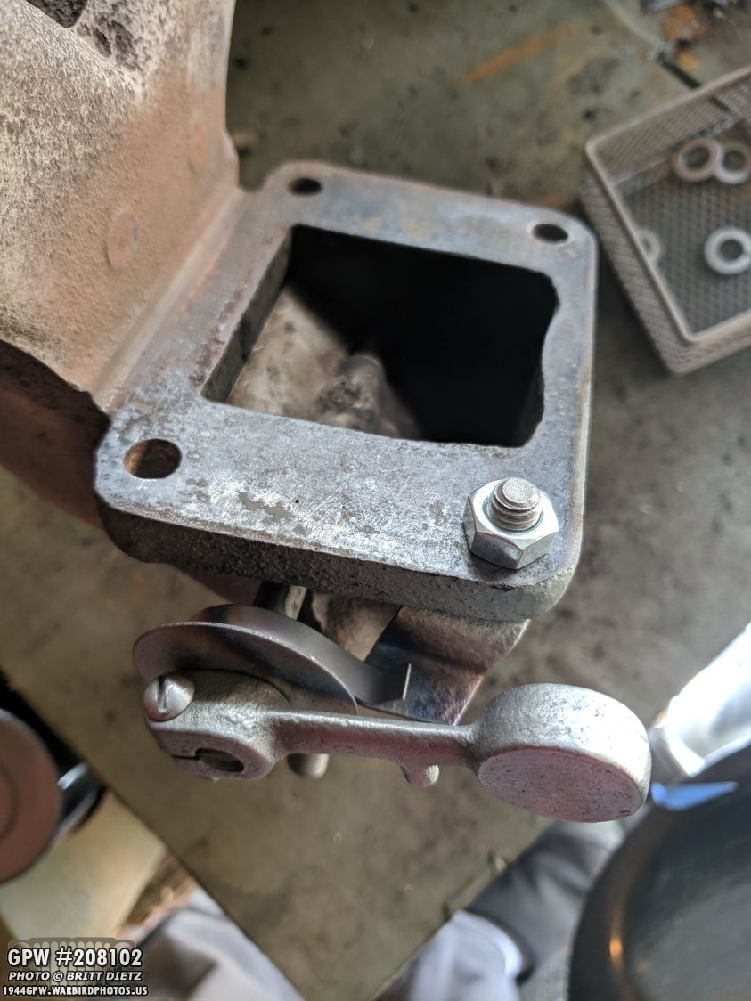
Here’s a look at the intake manifold (top) and the exhaust manifold (bottom, I’m keeping this one). They are only held on together with four bolts. The next step, now that both are apart, is to take apart the heat riser, which is installed backward. The red arrow is pointing to the riser, would should be pointing away from the engine, but it was installed backward, along with the spring, well before I got the Jeep.
It took a little bit of work, as the counterweight arm didn’t want to come off. But eventually, I was able to get everything taken apart.

I started to hand-sand everything, including the four bolts that hold the two manifolds together, but I realized I was wasting my time when I have a sandblaster in the garage.
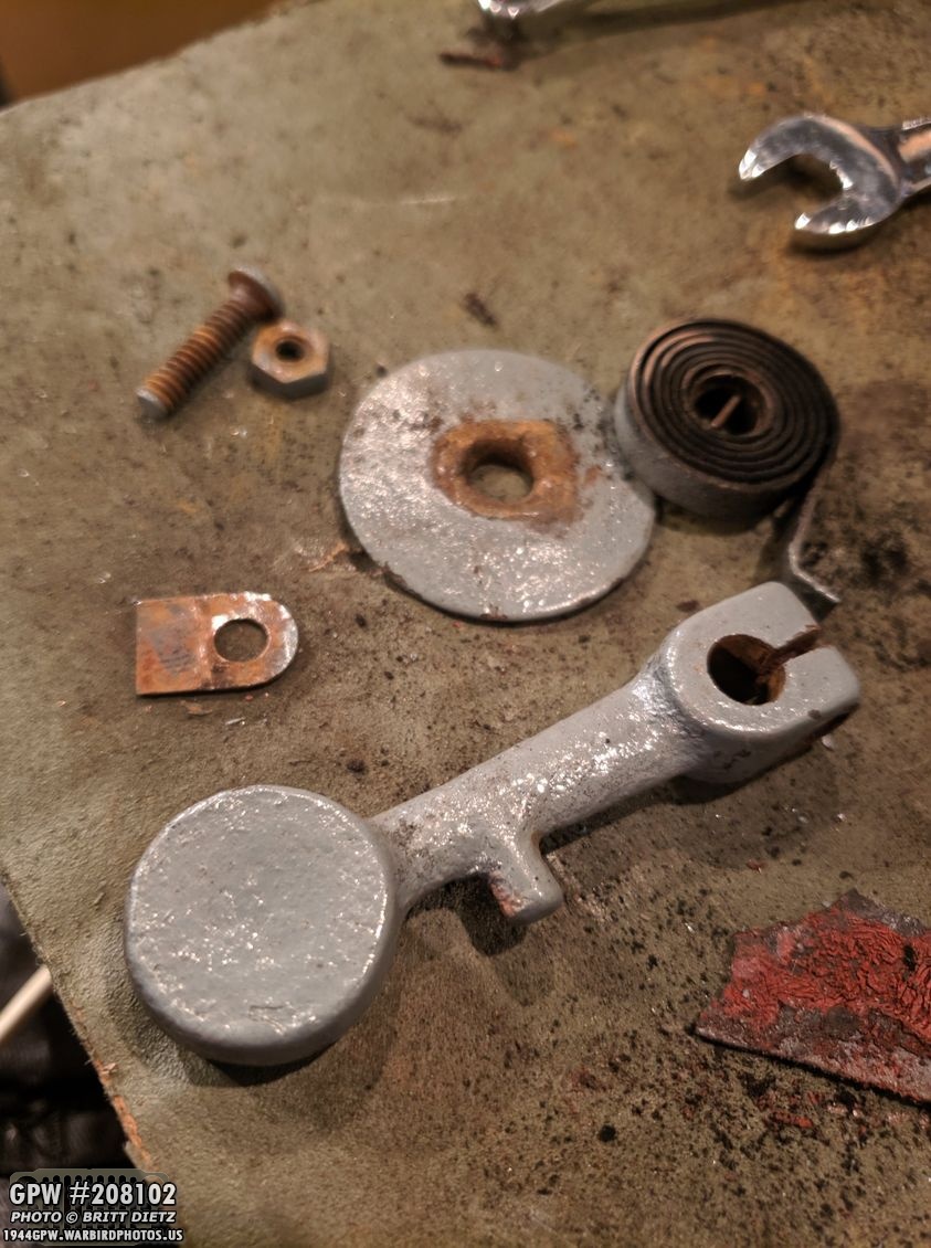
BOOM! All cleaned, even revealing a part number on the counterweight arm.

So, what does a heat riser do? And how does it work? It’s pretty ingenious. Let’s first tackle how it’s put together. A rotating flapper in the exhaust manifold has a stud that comes out the side with a slit partially down the middle.
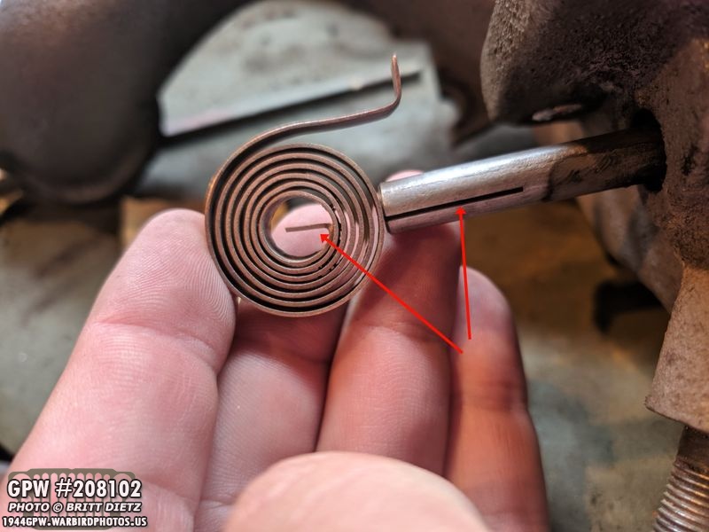
A coiled copper spring is put on this stud with the bent straight end in the middle sliding into the slit in the stud.

Normally, next a large washer is put on, but this I’ve left off for the demonstration. After the washer, the counterweight arm is put on, with a key put inside the stud slit. This key also slides into a slot on the counterweight. It’s all put together with a screw through the holes (goes through the counterweight, the key, then the other side of the counterweight).

This is what it will look like all together (this is before I sandblasted it) without the large washer, which is off to show this detail. What happens is at this down position, the flap is fully open. That allows hot exhaust gases from the engine to go both into the header pipe to go to the muffler and also up through the manifold and back into the carburetor to help with fuel vaporization. This is good for the initial cold starts to get the engine to warm up quicker. As the manifold heats up, the spring will uncoil from the heat. It pushes against the stopper (red arrow) making the engine spring turn, which then turns that stud everything is slide into (blue arrow). That in turn forces the counterweight up (yellow arrow) closing that flap and forcing all the gases to go straight to the muffler so the carb doesn’t overheat.
Here’s a look at the setup (with the large washer this time) after I took a burner and got the spring really hot. As you can see, it worked great. The counterweight is not lifted up and the flapper, inside the manifold, is closed! Great to have this working on my Jeep again!
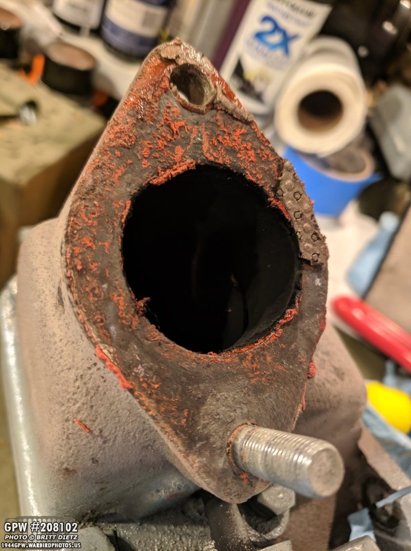
Another project was to clean off the bottom of the exhaust manifold so I can reconnect it to the header pipe (that goes to the muffler). I had used a new gasket and RTV to help make a good seal, so taking it all apart meant I’d need to clean it again. As you can see, bits of the gasket and the RTV remain after separating.

But with some sandpaper, I was able to make it nice and flat again.
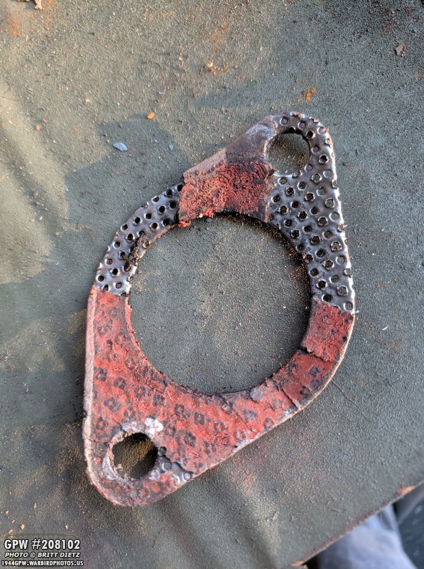
Sadly, the gasket was destroyed taking apart the manifold and the pipe, so I’d need a new one.

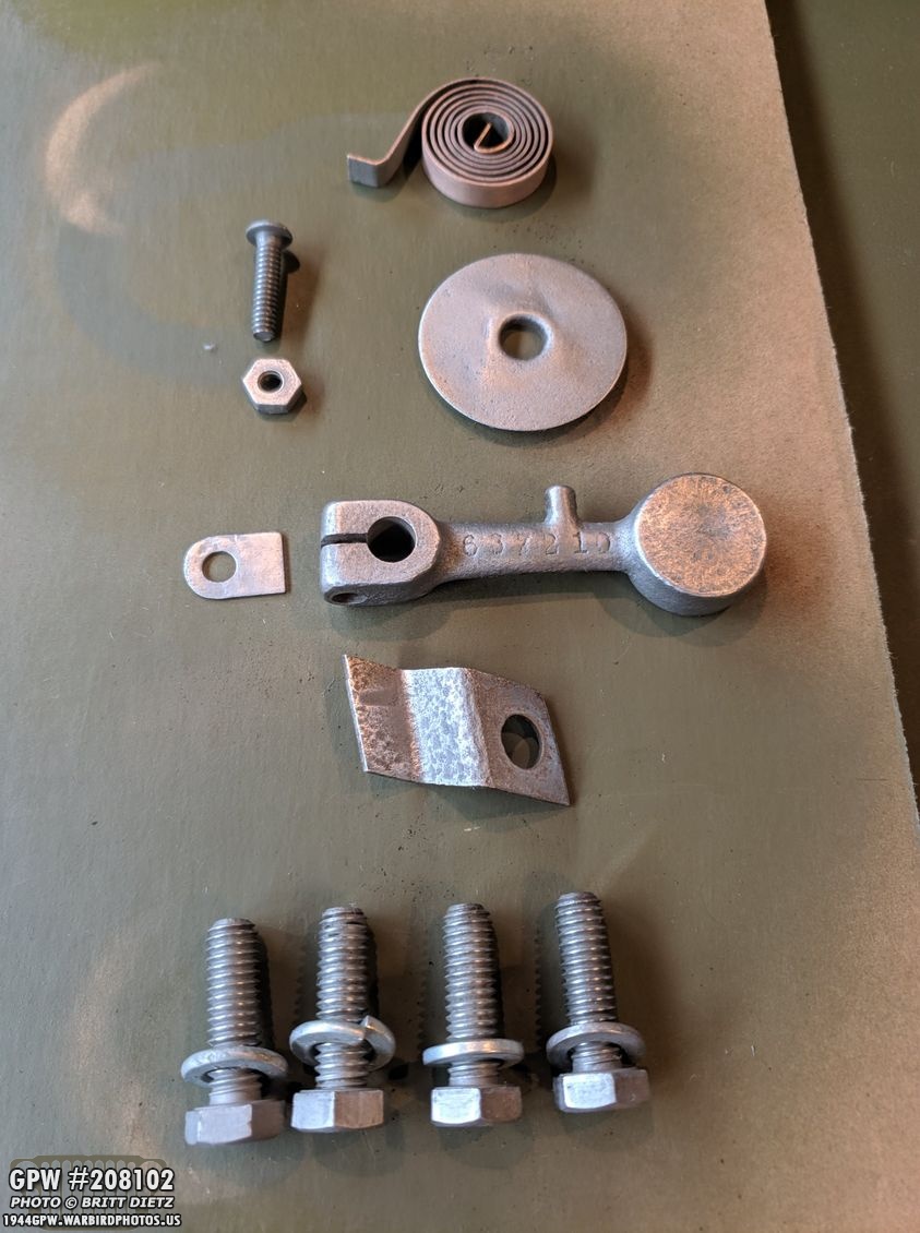
Which arrived a few days later, along with a new gasket to go between the two manifolds.

In fact, this adjusting the valves project required a bunch of new gaskets… including a new manifold to engine gasket, the intake/exhaust gasket, the manifold to header pipe gasket, and a new cork gasket for the valve panel.
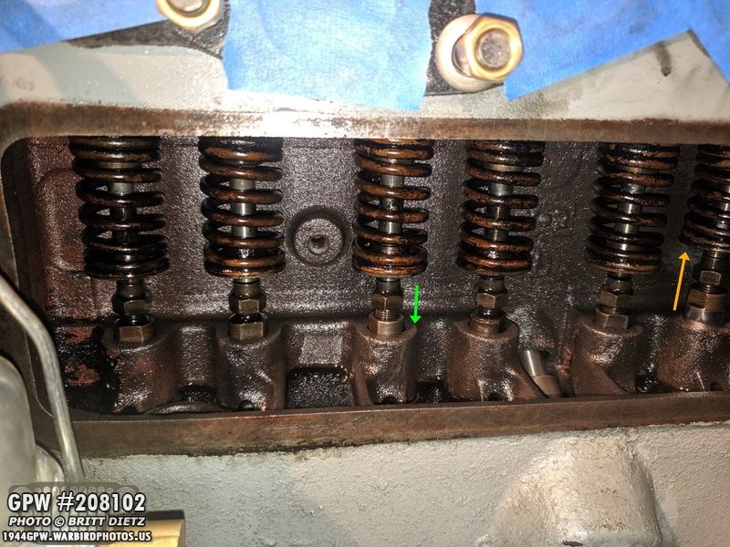
Speaking of the valves, it was time to adjust them! As the engine spins, these intake/exhaust valves go up and down depending where the main piston is. In this photo, valve #6 is pretty much up (yellow arrow). Using the rule of 9s, you do 9-6=3, so 3 is the one to adjust, which is pretty much at the lowest (green arrow). There’s a gap that appears now, which needs to be adjusted to exactly .014 of an inch. How do you do this?
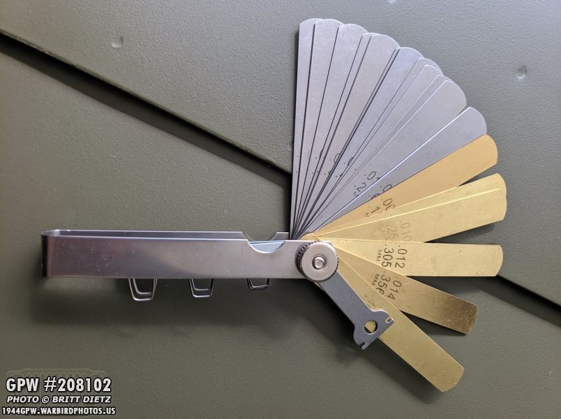
Using a feeler gauge. This one has a brass .014, which I would have not bought had I known it only had a brass .014 gauge. Take it from me, it’s easier to use a metal one!

So here I’ve turned the engine till the #8 valve was at the highest point. That meant that the #1 valve (9-8=1) is at the lowest. I’ve stuck the feeler gauge in the gap, and for this one, it’s a bit too tight. You want to have some resistance, but not too much and you shouldn’t be able to rotate the gauge and have any rocking motion.

So you take two 1/2 inch wrenches and turn the top nut counterclockwise to tighten, clockwise to loosen. After turning the nut only small amounts, you put the feeler gauge back in and check the clearance. Still too much gap? Then you tighten more. Too much tightness? Losen it until that feeler gauge goes in and you can feel slight resistance on the top and bottom. Do this for all 8 valves, turning the engine manually and watching for each valve to go to it’s highest point, and again use the rule of 9s to find the valve to adjust.

After adjusting the valves and checking my work twice, I went to work cleaning up the valve cover, which needed a new paint job.
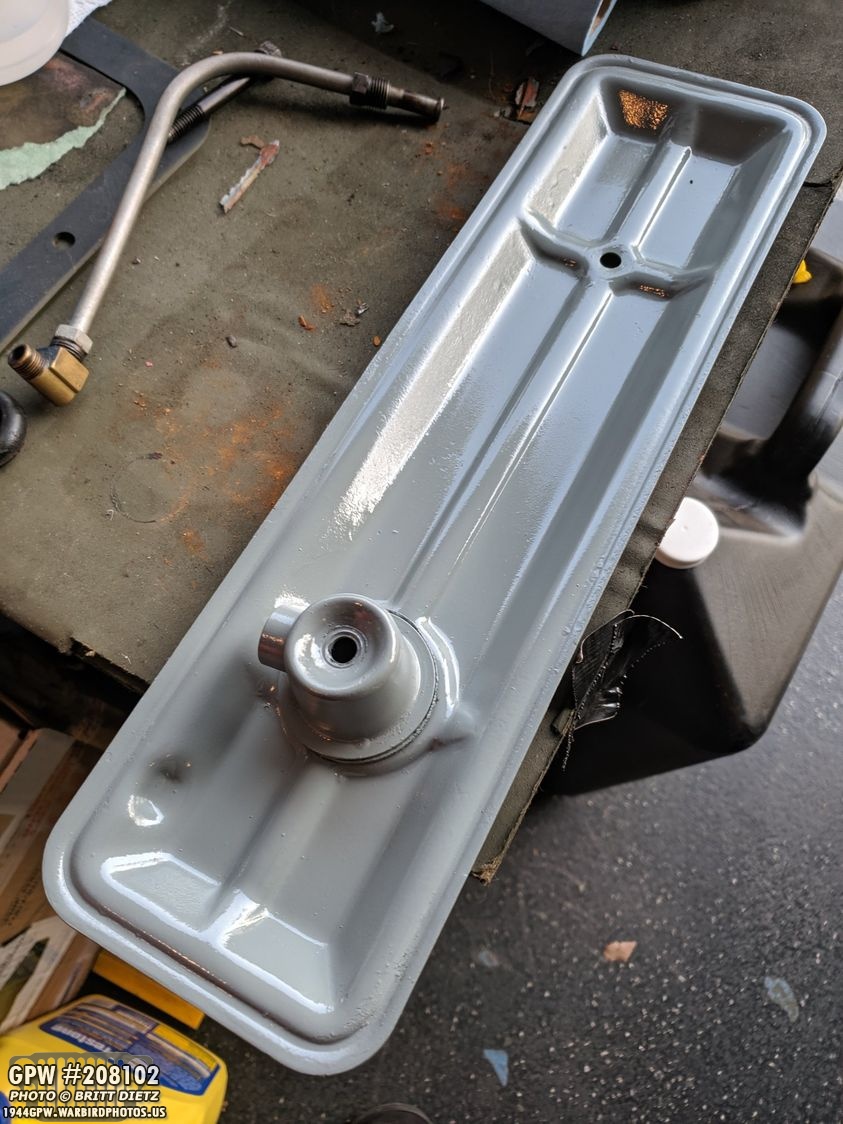
After some sanding and cleaning, here I’ve applied a new coat of Ford Engine Gray! All better!

Once dry, I added the new cork gasket.

And here the cover is back on the Jeep all tightened up! Next step will be to reinstall the manifolds once the new intake arrives. I won’t be adding RTV to the header pipe where it mates with the manifolds, and I want to test the engine to make sure that I got the adjustment right. If it sounds off, it’ll be easier to take everything apart again and not have to waste another gasket.

I was excited to get my markings stencils from Military Stencils By Axholme Signs this week all the way from the UK! Here’s all the stencils after taking them out of the tube. After this photo, I took several books and put them on top, getting them nice and flat after a few hours.

Here I’ve laid the hood number template on the hood to envision how it’ll look. This hood number came from the online hood number estimator which takes your serial number and gets a ‘roughly close’ number based on gathered data of Jeeps.
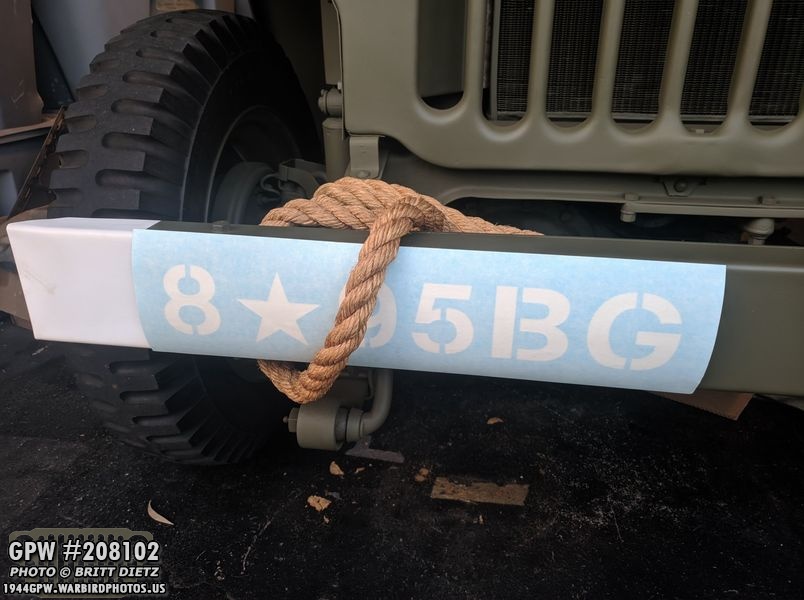
And here I’ve put the first part of the front bumper stencils against the bumper to see how they will fit. Can’t wait to put them all on!
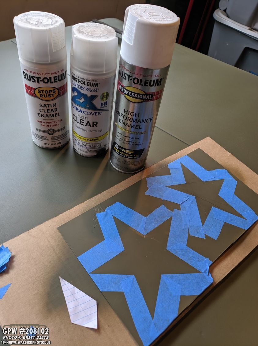
But, I want to make sure they last, as these stencils were expensive. Great quality, but I don’t want to have to buy them again for a long time if I don’t need to. They are one time use, so I have to get them right the first time. So picking how I want to do the white is important. I decided on high-performance enamel flat white from Rust-olenum as it resists fading, cracking, scratching, etc. But I’m thinking about also adding either a satin or matte clear coat over the white that has UV light protecting and anti-yellowing. So I used some painters tape to mask out two stars which I’ll be testing both ways to see what I like better and which holds up better when getting oil, grease, etc on them.

Finally, I had a helper this week as I was working on the manifolds, one of the cats decided to spend some time in the Jeep on the rear seat. Nice to have some company in the garage! That’s it for this week, I can’t apply the stencils because of rain here in California for the next few days, but hopefully, I can get the manifolds reinstalled and (if the starter comes back anytime soon) I can test the engine! Till then, see you next week!