 Setting a Ring and Pinion
Now that I have a second GPW rear axle ready to go, it was time to get to the one thing I don’t enjoy doing and has been an issue for quite some time… setting the ring and pinion. This update is not for the person who wants to do something easy, this is a LOT of work requiring lots of changes that can take hours/days to do. I’ve tried to simplify the entire process the best I can, and it’s still complicated! So join me on one of the most complicated processes to do on a Jeep! I also cover the removal of the ‘bad’ rear axle out of the Jeep.

Catching everyone up who might be new to this page, I restored and rebuilt a wartime GPW axle last year (along with a GPW front axle) to replace CJ ones on my Jeep. The rear axle ended up having a loud and strange ‘clackity’ sound from the housing. Rather than spending more time trying to find the source (which might never be found), I got another wartime GPW rear axle and I’ve started the process of restoring it.

Last week I finished the update by taking everything out of this new axle (we’ll call it AXLE #2). I was in the process of punching out the races (shown here punching out the outer bearing race).

Someone loaded the bearings on this axle with THICK grease. I have no idea why… these bearings get oil from the housing. That made things messy and was one of the reasons the carrier in AXLE #2 didn’t want to sping (along with it being incorrectly shimmed). As you can see, there were a ton of shims (top right).

I then pulled out the two inner oil seals with an oil seal puller.

That lefts a mess of sand? Dirt? I’ll have to clean all that out.

One thing I wanted to mention, using my Cricut machine I’ve started to make my own paper gaskets. Here’s the differential cover gasket, which I’m test fitting for the first time. Perfect fit! I design them in photoshop, take them over to the Cricut design studio, then I cut them out of cardstock paper.

After a deep degreasing/cleaning/washing/drying, AXLE #2 is ready for primer. I covered the spindle ends as they should not get any paint. I also gently pressed in the old yoke oil seal (with some painter’s tape sealing the hole closed) so protect inside the housing.

Alacazam! The axle is primed! It was a nice warm day, so I was able to get two really good coats on.

I used a spare cover from a CJ2 (which is the same bolt pattern and size as the ww2 ones) to cover the housing to finish painting this side. I’m using the gpw cover from AXLE #1, which is already painted, so I didn’t want to use that here for priming.

Now to remove AXLE #1 from the Jeep! I’ll need the parts from it for AXLE #2. Using my lovely 1 ton Harbor Freight crane, I lifted the rear of the Jeep so the wheels were off the ground.
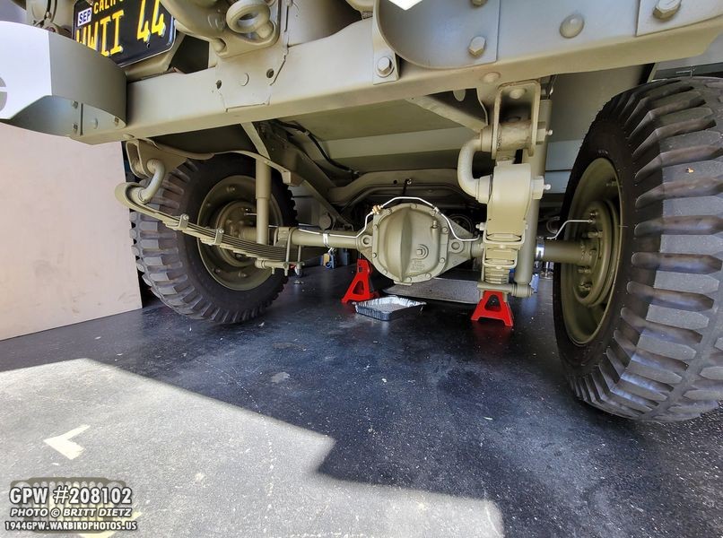
I could then put the jack stands under the Jeep, elevating the wheels in the air.

First off is the tires and combat rims!

Since I’ll be stealing the carrier, ring, and pinion for AXLE #2, I went ahead and drained the oil from the housing. As expected, there were metal shavings (which is part of the clackity sound, we’re suspecting).
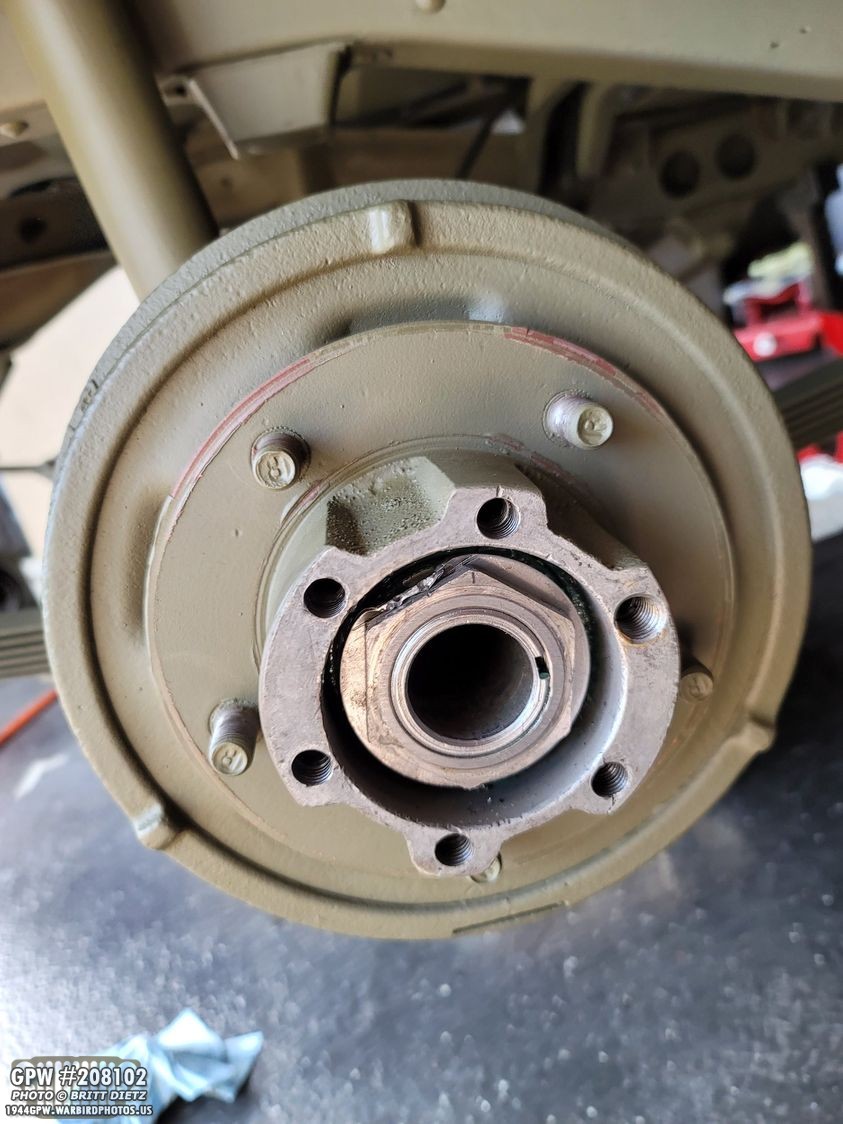
Next up, moving onto the drums.

When I restored AXLE #1 back in December, I peened over the large washer (as you’re supposed to do to lock the outer nut in place), so I had to ‘unpeen’ that by tapping it with a punch.

With the nut free, I could take my large GPW hub socket with a rachet and remove the nut.

After the nut, I removed the large washer, the second nut, and the small washer. I could then pull off the drums.

This is as far as I wanted to go with the wheels before taking out the axle.

I put a shop towel over the exposed bearings in the drums and set them aside. Don’t want any debris getting those bearings!

The axle is ready for removal! Now I need to move on to the springs.

I went ahead and removed the carrier to lighten the axle.

Next, I disconnected the brake line from the flexible line to the long line that meet at the rear crossmember. I wrapped both ends in a plastic bag and taped the end which will hold the bag on the end tightly. You don’t want anything getting in there.

Things were going fast… I removed the U bolts, the leaf spring plates, and disconnected the shocks from the bottom.

I then removed the shackles and lowered the springs. I decided to use the transmission jack to help me roll out the carrier. This little thing is totally worth every penny!

And just like that… the AXLE #1 is out!

I removed the rest of the items including the pinion and the brake plates.

AXLE #1 is all done. I’ll sit that aside as I decide what I’m going to do with it.

I did take a moment to lightly sand the springs where the axle sat on them, and primed them. I’ll paint them OD Green later.

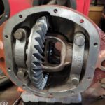
To get started on setting the ring and pinion in AXLE #2, we will need to check the runout on the carrier. In AXLE #1, the carrier had a pretty extreme runout (over 10 thousandths on the dial indicator). So I needed to check it in the AXLE #2 housing.

In total, I have THREE different GPW carriers. Why three? Carrier #1 came with AXLE #1, but it was damaged during the spider gear explosion that messed up the axle. So I went and got a take-off GPW carrier, number 2, which I then put in AXLE #1 along with a NOS GPW ring and pinion set. AXLE #2 came with carrier number 3. For simplicity sake, I’ll refer to the last two carriers as #1 and #2 for their respective axles. Meaning carrier #1 (2 in this photo) was in AXLE #1. Carrier #2 (3 in this photo) was in AXLE #2.

So here is Carrier #1 from AXLE #1 in AXLE #2. I was afraid it would be tight, but it slipped right in no issue.

There are two ways to check runout, or how much ‘wobble’ the carrier and ring have. One way is to measure the back surface of the ring gear.

You use a dial indicator and spin the carrier all the way around finding the highs and lows. You then count the number of notches. 1 notch is 1 thousandth. I checked both carriers, shown here is carrier #2… it only had about 4-5 thousandths runout. Carrier #1 had over 10 still! Yikes.

But you have to check the carrier itself, as the ring could be warped causing the runout. To do this, you need to remove the ring from the carrier, and put the dial indicator here. Spin the carrier, and again check the highs and lows. It was the same, carrier #1 was about 10-11, Carrier #2 was 4-5. Carrier #2 was in spec, while carrier #1 was well out of spec. So, I decided to use carrier #2 with the NOS ring and pinion from carrier #1.

Let’s take a look at carrier #2. I removed the bearings since they were packed with grease and not in good shape.

No F stamps on it, but it had the proper GP and part numbers. It’s possible it’s an early carrier. There’s an odd machine screw head on the carrier. I can’t tell if it’s cast or an actual screw that was added for some reason and it’s become one with the carrier over the years.

One interesting thing to note is one side of the carrier where the bearing goes on, there are all of these small little holes punched in. I found out, these are ‘peened’ holes that mushroom out the area around the holes, causing the bearing to ‘stick’ better if the flange has worn out over time. It’s very well done.

I then removed all the spider gears and grouped together the shims for each bearing. I’ll be using the spider gears from carrier #1 in this carrier, as they are in pristine shape (and I recently replaced the thrust washers and pins).

To quickly measure the runout of carrier #2 with ring #1, I put the bolts on with the ring. No need to add the lock straps as this will be coming off again.

Checking the runout, it was still 4-5! Winner winner.

Taking it back out and removing the ring again, I installed the spider gears, thrust washers, and pin from carrier #1. Perfect fit.

I then went back to AXLE #1 and removed the pinion, spacer, and yoke.

Another thing I’ll be using from AXLE #2 is the pinion spacer. It’s on the right VS the spacer from AXLE #1 on the left!
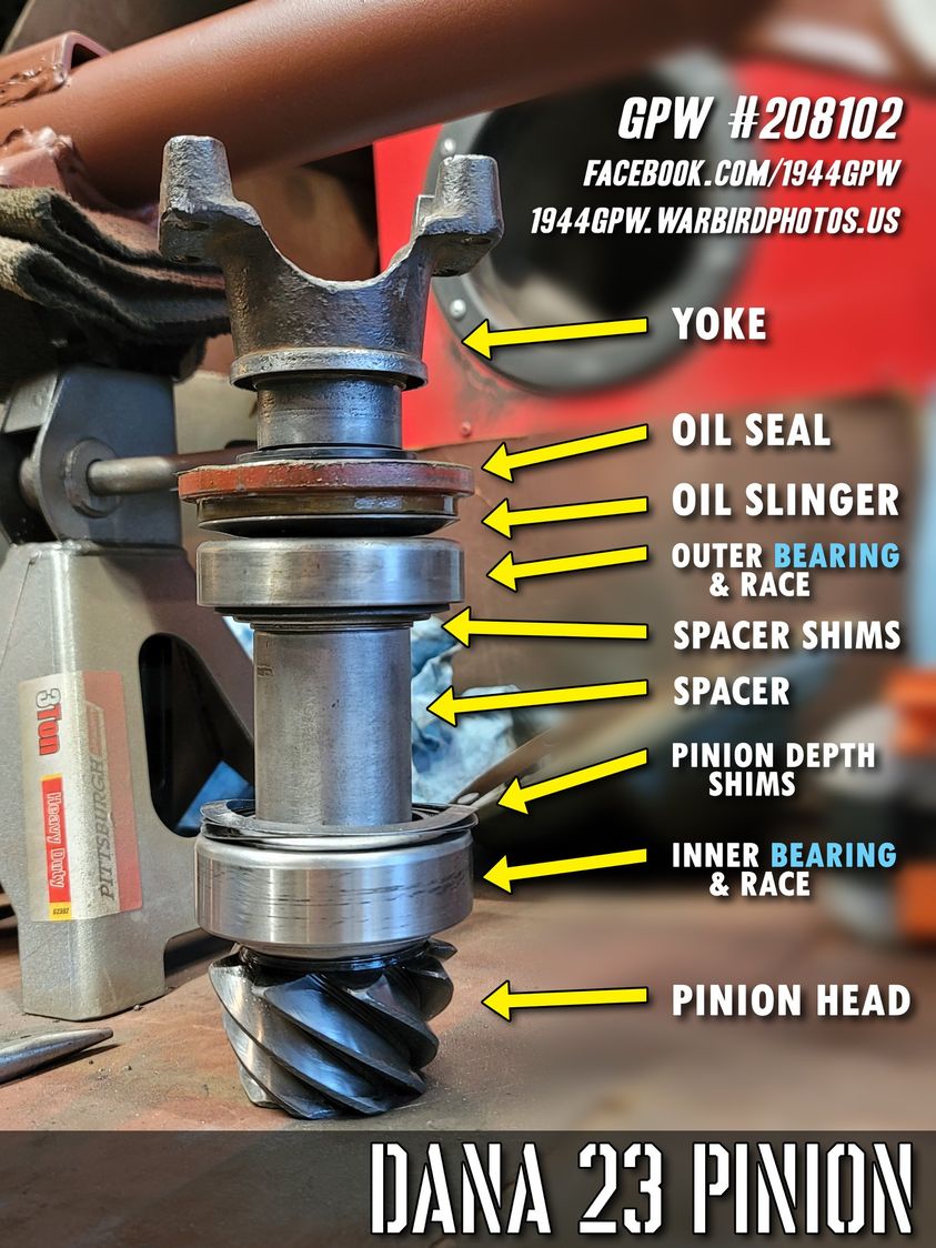
So now that we have things ready… let’s go over the parts of a pinion and carrier. Let’s start with the pinion as that’s what we’ll start with when setting it. You have the pinion itself, then the inner bearing and matching race (or cup). Next, you will have shims. These shims set the pinion depth, or how close or far the pinion sits from the carrier. These will be something you will end up hating most. Next, we have the large spacer, and on top of that is another set of shims. These smaller shims set the distance between the two bearings (lose or tight). You have the outer bearing with race, and oil slinger washer, the oil seal (which we won’t need for setting things up), and the yoke.
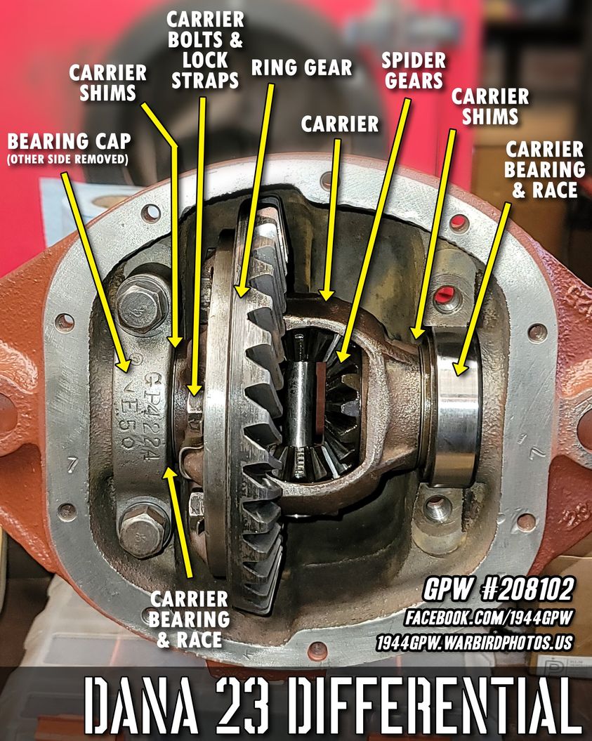
Now, we have the differential, which is the carrier in the housing. This is made up of the carrier itself, which on either end has a bearing, race (or cup), and a screwed-in ‘cap’ that holds it in place. There are shims between the bearings and the main carrier. These will play a big role coming up. The carrier has the ring attached with bolts and lock straps that stop the bolts from spinning off. Inside the carrier are the spider gears. This is a bit simpler than the pinion parts!

Unless you have a really nice hydraulic bearing puller (I do not), and if you want to make this process go faster, I highly recommend using a ‘donor’ set of bearings for the outer pinion bearing and the two carrier bearings. You will be taking them off a LOT. Since I was getting all new bearings, I used the ones from carrier #1 (which are newer). I used a Dremel to grind the inside of the bearing, which will allow it to go on and off the pinion with ease.

And I Dremeled the inside of the bearings for the carrier. This will be the most helpful thing, as these bearings are a serious pain to get off. Not to mention having to get them off and on several times. These will forever be my ‘special’ bearings, so if I ever need to do this again in the future (I hope not!) I have them.

I also used the really beat-up yoke from AXLE #2 in the same manner, I used a Dremel to carve out the splines a bit more to make it easier to get on and off, as you’ll be taking this off a LOT. My good GPW yoke from AXLE #1 will be the final one I put on when everything is set.

And don’t worry, I have new bearings from Ron Fitzpatrick Jeep Parts ready to go once I get things set!

Let’s get started setting the ring and pinion. You will need shims for the inner bearing (the ones you’ll hate), the carrier shims, and the pinion spacer shims. Each of these will do something different… the inner bearing shims set the pinion depth or how close or far the pinion head is to the carrier, the carrier shims set the left and right placement of the carrier bringing it closer or further from the pinion, and the pinion spacer shims set the distance between the two bearings on the pinion (tighter or looser). These sets, available all over online, will come with all sorts of different thicknesses. Having a digital caliper will help when you need to make precise measurements of the shims.

Looking at pinions, most pinions will have two markings on the head, shown here. On the left is Pinion #1, the NOS one I had gotten, it doesn’t have any markings which is very odd. Pinion #2 has a 5 etched into it, which is actually the factory set depth the pinion should be set to. This is great if you have a WW2/1940s pinion depth tool. Sadly, those are very rare and hard to find, so we’re going to have to act like we don’t know the depth.

First thing, gather some shims for the inner pinion and place them into the housing where the inner pinion race (or cup) will be driven in. As you can see from these shims, I’ve put them on and punched them out several times now. I’d say, start with .030 worth of shims in whatever combination. You’re going to have to do this all again unless you’re super lucky.

After the shims are in, carefully drive the inner pinion bearing race, or cup, into the recess. Use a punch and gently rock it back and forth seating it down all the way until it’s flat against the shims. You want to make sure it’s seated as far in as it will go.

Next, drive in the race for the outer pinion bearing. This is the ONLY thing you won’t have to remove over and over during this process. This will only have to be removed once you have everything set and you’re putting in the final bearing/race.

No we’re going to insert the pinion. Place the big spacer on first, then, slide on shims on top of that spacer. Again, these shims space out the two bearings, making the pinion turn tighter and looser. You can start with .030 for the shims here as well. We’re going to get this set first.

Place the pinion into the housing this way. You’ll need to then rotate the housing over, so hold the pinion in there with one hand.

On the other side, insert the outer bearing. If you Dremeled out the inside, it should just slide on no problem.

Then put on the oil slinger washer.

While you’re still holding the pinion inside the housing (otherwise it’ll just fall out since that bearing isn’t holding it in place), put on the yoke. (Forgive the fact that the oil slinger isn’t on in this shot, forgot to put it on for this photo but realized right after). Tap on the roke with a hammer till the threads for the pinion stick out. If you dremeled the inside of the yoke as I did, it’ll go on easy but still hold the pinion in place. You can now let it go from the inside.

Now, put the washer and castle nut on the end. If there’s not enough thread, tap on the yoke a bit more with a hammer till there’s enough. I then used an impact air gun to full screw on the castle nut.

Now we can check the first part. Make sure the castle nut is full on, then pull up on the yoke. Does the pinion (with the yoke) go in and out? Then the spacing between the two bearings is too much, you’ll need to REMOVE shims from the spacer. Is it tight to where you can barely turn it and it doesn’t pull in or out? It’s too tight, and you’ll need to ADD shims to the spacer. Does it no pull in and out, and have a bit of resistance (just a bit) when turning? Then you’ve probably got it right where it needs to be. So what if you need to change the shims? First, remove the castle nut (shown here)…

To get the yoke back off, you’ll need to use a bearing puller like this. If you Dremeled the inside, it should come off somewhat easy, and MAKE SURE you have your hand inside the housing holding the pinion because when the yoke gets loose, the pinion will fall out of the housing and onto the table!

With the pinion out, you can now add or remove shims from the spacer, shown here. You may have to do this entire process several times until you find the perfect amount of shims needed to have the pinion not move in and out but freely turn with a bit of resistance. If you have a fish scale, you can use it to turn the yoke and shoot for 3-4 pounds of torque pull.

Assuming you have found that sweet spot with the shims, go ahead and put that castle nut back on tight.

Now it’s time to set the carrier. Place the carrier into the housing, as shown. You can start with no shims under the bearings. Move the carrier over to one side (using a screwdriver, etc) so it rests to one side (yellow arrow). Then, take a feeler gauge and measure the gap between the bearing race and the housing on the other side (green arrow). Let’s say it comes out to .030 feeler gauge. That would mean you should put .015, of half the feeler gauge, worth of shims on EACH SIDE under the bearings. So .015 on the left, and .015 on the right. This should made the carrier so it’s snug getting in where you might need to do a light single tap with a rubber hammer, but you can still mostly put it in and out.

Shown here is the bearing pulled off one side, and shims slide onto the carrier flange. I’ll then put the bearing back on. Again, it’s easy to do when you have bearings that pull on and off! Otherwise you’ll need a special bearing puller because of the minimal clearance with these bearings.

Once you have even shims and the carrier goes back in nice and snug, set up a dial indicator on one of the teeth of the ring. Holding the yoke with one hand tightly so it won’t move, very gently rock the ring back and forth. If you feel is slightly rocking, that’s called backlash. This is what we’re measuring. If you feel no movement whatsoever or if you spin the carrier it’s super tight when turning, there’s no backlash. No blacklash is bad, too much backlash is bad. What you’re looking for is that super slight rocking movement, which will measure only about 3-7 notches on the dial indicator. I was getting about 4.5/5, which is perfect. So what to do if there’s no backlash or too much?

Take out the carrier, take off the bearings, and you will have to transfer shims from one side to the other. The next photo explains how.

If you move a shim from the left, shown here, to the right… that will move the ring away from the pinion, this will ADD backlash or loosen the ring movement. If you move a shim from the right to the left, that will move the ring closer to the pinion, this will REMOVE backlash or tighten the ring movement. You may have to do this several times till you find that sweet spot. Once you have that set, you have 2 out of 3 things done (for now, you may have to check it all again after the last step).

Now we’ll do the grease test. Some people use special oil based paint. I use white grease (which I’ll have to clean off completely when this is all done) because it’s what I have. What we want to see is how the pinion contacts the teeth of the ring. The pinion needs to contact the ring teeth perfectly centered. So, put some grease (or whatever you want to use) on a few teeth as shown. I did a lot here, you really only need to do 4 teeth, and maybe in two other spots as well on the ring).

Now, hold the yoke with one hand and rotate it counterclockwise. With the other hand, push down on the ring and push down so you’re coutering the way it’s turning. This simulates ‘load’ on the carrier. After the grease has passed through the pinion, you can see how the pinion has moved/cleared the grease. In this first attempt I did, you can see the completely cleared-off area is at an angle towards the outside of the teeth. That means the head of the pinion is too far away from the ring (or too far forward in the housing). Sadly, this means we have to start again to change shims for the inner bearing on the pinion changing the pinion depth. What does that mean?

Well, we will need to take everything out except the outer pinion race. So, the carrier caps, the carrier, the castle nut, the oil slinger, the outer bearing, the pinion itself, AND you’ll have to drive out that inner bearing race. Yup, this will take you a long time.

As shown here, this is where we need to make adjustments, those shims we put behind this race need to change. In orde to drive this out, drive it out with a punch rocking it back and forth through the outside of the housing. There are two little slots cut into the lip the shims/race rest on that allow you to punch it out. This will leave marks in the shims, so you will need to re-flatten them once you get the race out.

Now comes the time to make the change. It’s a bit of a guessing game here, but here’s what you need to do…
– If the grease test shows that the pinion is too far away from the ring (forward) like my test showed, you will need to ADD shims so it’s closer to the ring.
– If the grease test shows that the pinion is too close to the ring (backward), you need to REMOVE shims so it’s further away from the ring.
In my case, I added more shims.
Because you’ve changed the shims for the race, you should do the opposite you did with the race shims, but with the same value. So, if you took away .010 from the race shims, you should ADD .010 to the spacer shims. If you ADDED .010 to the race shims, then you should REMOVE .010.

Now you can do it all over again… Drive back in the race. Add the pinion. Put on the outer bearing, oil slinger, yoke, washer, and castle nut and get it all the way on. Check for the tightness of the yoke again and make sure there’s no in/out movement and it’s not too loose or tight. Then put in the carrier, recheck the backlash moving shims left or right to get that 4-7 on the dial indicator. Then, once that’s all set… do the grease test again. See why this is all SUPER tedious?

After I added shims to the race shims, I put too much in. UGH. Now, the pinion is too close to the carrier (backward). So, now I need to remove half the amount I just added. So, start the entire process over AGAIN. Each time you do this, expect about 30 minutes of taking it apart and putting it back together. Add extra time if you’re getting frustrated.

I ended up doing this entire process several more times, having to make adjustments to the yoke tightness (spacer shims), ring backlash (carrier shims), and the pinion depth (race shims). I’ve gotten it close, but I still have some ways to go as shown here. This might look a bit different than the last two tests, and I’ll explain why in next week’s update (basically, had to use a different ring/pinion). So, how should the grease test look?

This is back when I had help setting the ring and pinion for AXLE #1 when I restoring it in December. Here you can see a perfect impression. The pinion is evenly taking the grease off the ring teeth. If you get this, you’ve got it! BUT, keep in mind, when you take off your ‘test bearings’ and put on your good bearings, there’s a good chance you might have to adjust things again, meaning you’ll have to pull those bearings off. This should get you right there and close or at the very least in the ballpark.

So that’s how to set a ring and pinion, as easy as I could think of making it. I HIGHLY recommend you go onto youtube, there are several great videos showing this entire process from start to finish out there that will help if you need to see in video what I’m explaining here. It’s going to be a lot of frustrating work, as I’ve been told doing this is not an amateur thing to tackle, and most people I know take their axles into professional shops to have this done for them. If I had that option around here, I might even do that. But, it’s good to learn, and while I’m frustrated, I’ll eventually get it. Until then, my Jeep sits without a rear axle.
Till next week…