 Drag Links, Wheel Alignment, Brake Bleeding…
Work continues at a rapid pace with the GPW axles! With the CJ axles GONE, the wartime restored GPW axles are going in. This update is packed with things from the installation of the GPW drag link, adjusting the steering, finding a solution to the bending spring leaf plates, setting the wheel alignment and toe-in (with a diagram!), and finally… bleeding the brakes!

Wait what, the Jeep looks done?! Well, it’s not technically… but I wanted to remind everyone reading along that I’m actually about a week ahead of the updates (give or take a day or two). Because Facebook is limited on how many photos I can post in one update, I’ve had to break up certain things and days to multiple updates. So let’s get started!

Last week I got the front axle installed with the springs and shocks. I also finished the torque reaction spring, which is the first time this Jeep has had one in probably 40-50 years!
Now it’s time to add the drag link to the bell crank on the axle! Before, the Jeep had a CJ drag link as the CJ front axle has a different steering system.

Earlier last year, I bought this take-off original GPW drag link (with a FORD mark on it!). It was sandblasted, cleaned, and painted and has been awaiting install! That, along with my special drag link cap screw driver socket I created.

Using the TM 9-180 is the best way to figure out the internals for the drag link. When I restored the CJ axle in 2019, I went through this in depth as both the CJ drag link and the GPW drag link, though different lengths and shapes have the same internals. The bell crank (front) side has the cap (or plug), a ball seat, spring, and spring seat. Then the bell crank ball will press against that. On the pitman arm (back) side, there is the cap, spring seat, spring, and two ball seats unlike the front.

First up, I put the dust seal shield and the rubber dust shield on. This needs to go on first to both the bell crank and pitman arm. Once that’s done, and the drag link loaded with the internals, I greased up the bell crank ball and pressed it into the drag link. I then put the cap screw in just hand tight.

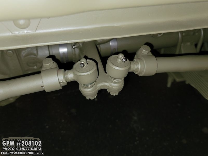
For the pitman arm side, I pre-greased the two ball seats.

Then I took the other internals, and put in the pitman arm after pre-greasing the ball.
And then I was able to slide back down the dust seal and shield. I then screwed in the cap screw.

To properly screw in the cap screw (plug), you need to screw it all the way in till it stops, then unscrew it 1/2 turn. Make sure at least two of the holes line up to put the cotter pin through/ Once that is in, you can bend the cotter pin around the sides to lock it in place.

Here’s the same thing on the other side.

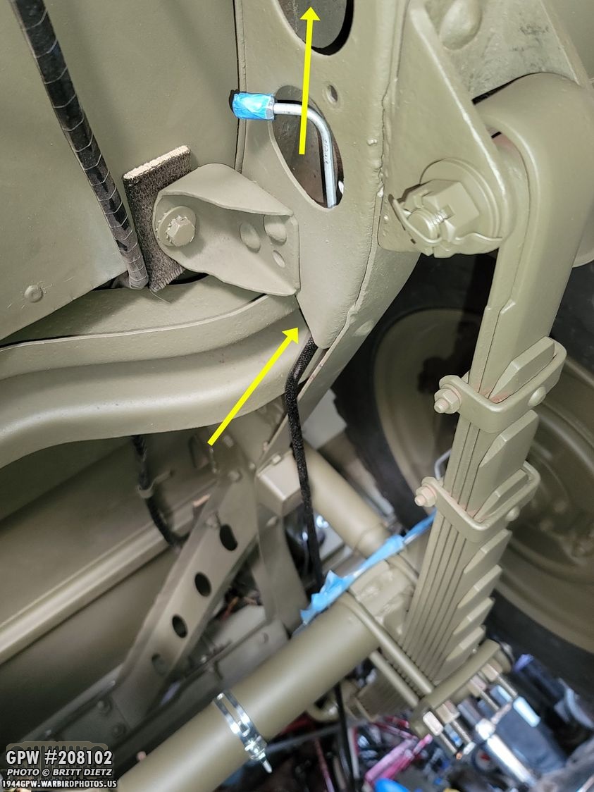
With the drag link installed, I went to work adjusting the slop on the steering. You want to have it where the steering wheel free play was only 1/8 of a turn. Meaning, the wheels won’t move for no more than 1/8 of a turn. Anything more than that, and the steering box needs to be adjusted. To adjust that, you go to the steering box (really tight fit), unscrew the nut (yellow arrow) so the inner slotted stud (green arrow) can then be screwed in to tighten the steering, or screwed out if it’s too tight. Then once it’s set to where you like, you tighten the nut to lock it in place.

With that, the front is all installed! But more adjusting is needed.
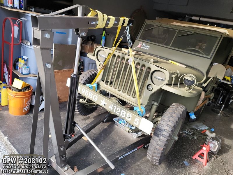
The rest of the adjusting needs to be done under load, so it was time to take the front off of the jack stands! I used my 1 ton crane to lift the Jeep up to take out the jack stands. A Lot easier than jacking up the bottom and messing up the paint.

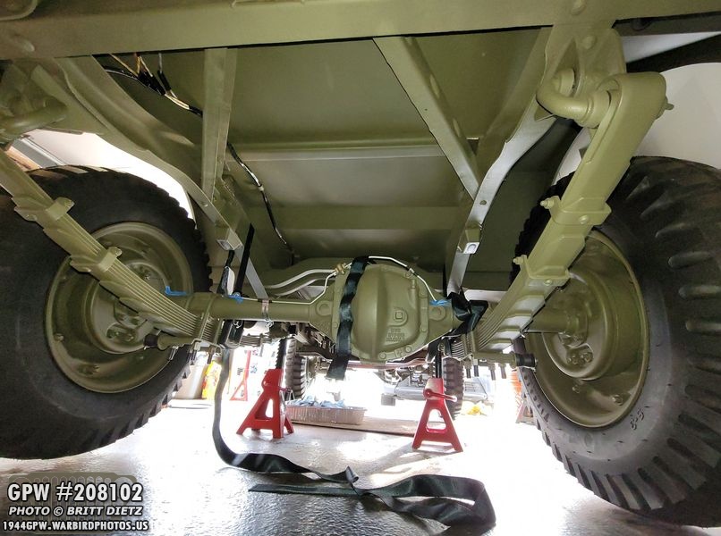
With the front down, the Jeep was on both the front and back GPW axles for the first time!

I had been told the Jeep would have a ‘lean’ to the driver’s side because of the torque reaction spring (and the fact that the driver and fuel tank are on one side. Putting a level on the front bumper, you can see it does indeed have a lean, but it’s honestly not as bad as I thought it would be.
With the front back down, I moved back to the rear of the Jeep, lifting it up and putting it back on jacks.

If you’ve been following along the last few weeks, you’ll remember that when I put the repro spring leaf plates on the rear axles, they seriously bend upwards applying only about 40 foot-pounds torque. Considering the TM manual states that it should be between 50-55 foot-pounds torque, I had to figure something else out.

Taking off the leaf plates, you can see just how bent they got. I found out from the vendor that they are made with mild steel, so they easily bent around the scalloped edges of the GPW style springs.
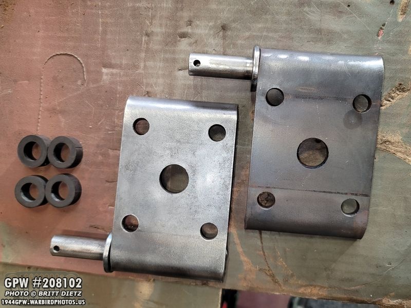
I was suggested on one of the Jeep groups to check out Walcks4WD’s leaf plates. So I took a gamble and ordered a set for the rear, which arrived a few days later.
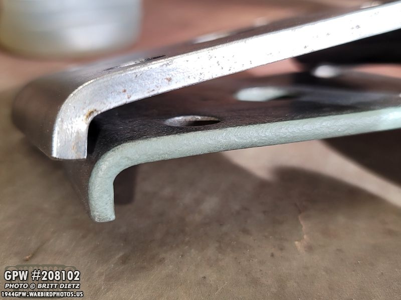
To my delight, these leaf plates are THICK and much heavier, appearing to be made from tougher steel. They are even thicker than original leaf plates (on the bottom of this photo with the new plates on top).

Here’s all three compared… the top (yellow arrow) is an original plate, the middle (green arrow) is the Walcks4WD plate, and the bottom (red arrow) is the other vendor’s leaf plate that bent.

After taking off the bent plates, I had to actually straighten and re-thread the u-bolts as they had pigeon-toed out with the bending plate. Ugh. I got them as straight as I could and the thread back to being perfect.
I have to admit, I was nervous putting on the Walcks4WD plates due to my bad luck… but I started to put on the nuts and hand tighten them…

I torqued them to 30 foot-pounds… no bend. So far, so good. 40 pounds, no bend. 45, no bend. 50 no bend! I decided to stop there, as that was within spec. Here are the four nuts torqued to 50 foot-pounds, no bend! I was so delighted!

Moving on to the other side and feeling better about it, I torqued it straight to 40 foot-pounds, no bend! Then to 50 no bend! YAY! THANK YOU Walcks4WD!

With that in, I could finally permanently install the shocks with the rubber bushings, washer, and lock washer.

The top cotter pin wasn’t too hard to put in. I was able to push in the washer enough to get the cotter pin through. I then bend it over.

The bottom of the shocks was another story when the thick washer went on, it almost completely covered the cotter pin whole and didn’t want to compress in enough. UGH. I managed to get it without any special tools (just brute force with my fingers) but I had to put the cotter pin in upsidedown. I don’t mind, in fact, it bent over better this way.

After the cotter pins were installed, everything was touched up with OD Green paint! Shocks are done and the axles installed!

I then took some painter’s tape and covered up the brake lines so I could tough up the paint on the U bolts, axles, and springs where everything rubbed while installing. I also put the Jeep back down on all four of the wheels. She’s taking shape!

Next up, wheel alignment! First, I started with the string method to get a basic wheel alignment, where I taped a piece of tape to the rear wheel backside, then held it straight and touched it to the front of the rear wheel, then the back of the front wheel. If the front of the front wheel also touched, they were all lined up. If not, then I needed to adjust the tie rods to rotate the wheel in and out.

In order to adjust the tie rods, I made sure to loosen the clamps on the tie rods (two on each side of each tie rod) so I could rotate the tie rods. I ended up not liking the string method, so I went another route.

I decided to use the method of using the center of the front tires to align them. The basic principle is that if the distance between the centerline of the tires (which my Jeep has since these are new tires) is the same on the front and back of the front ties, then the tires are mostly aligned. Once you get to that spot, then you can adjust the ‘toe in’, or the slight inward turn both tires need to be to eachother. I’ll explain…

Here’s a diagram on how it works. 1) Using the centerline of the tires, you measure the distance between as high as you can on the rear of the front tires, then the same height on the front of the front tires. To start, make them the same distance. 2) To make the tires turn in and out individually, you have to turn the tie rods. Your Jeep may vary on which way turning the tie rods will turn the wheel. But you turn the passenger side tie rod to turn the passenger tire. And the driver’s side tie rod turns the driver’s side tire. 3) When you turn the tie rods, turn them both the same amount. So if you turn the left tie rod one turn, turn the right tie rod one turn. 4) Remember that when you turn the tie rods so it turns the wheels in and out, if you turn it so the FRONT of the tire comes in, remember the BACK of the tire will go out. So it’s a bit of a back and forth moving the wheels out and in until both the front and back line up.5) After they line up, you have to set that toe-in. You want to turn the front of the wheel a hair inward so it’s 1/32 of an inch less than the rear. That comes out to a difference of 1/16 inch, which is the proper toe-in. Hopefully, that makes sense!
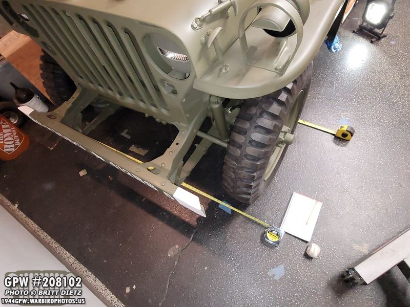
Here’s a look as I was doing the measurements with two measuring tapes. It helps to have a second person to hold the other side of the measuring tapes as you go back and forth, and also so they can watch the tire movements as you turn the tie rods.

Once you get the proper toe-in and everything is set, you can then tighten the four clamps. BE CAREFUL that, as you tighten them, they don’t turn the tie-rods! That could misalign things.
After that, I went ahead and painted the tie rods.
Nice and tight, aligned, and painted!

And this side. I will say, I checked and double-checked the toe-in alignment several times. I was probably WAY more critical of the alignment than most people are, but I wanted to get it right by the TM manual.
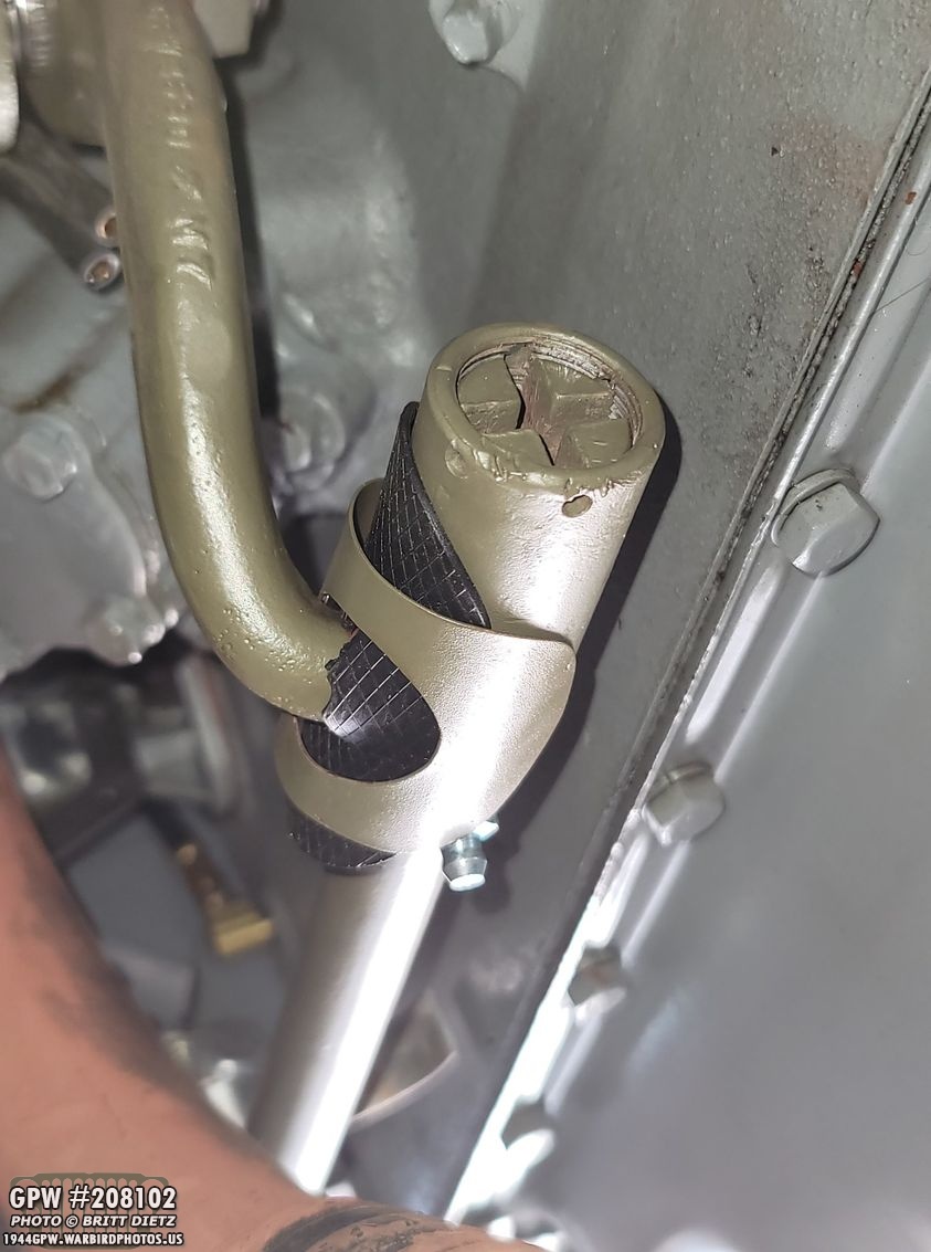
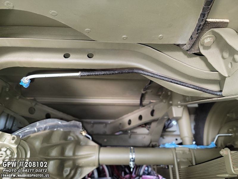
Next up, time to install the last brake lines! After taping up the ends of the long brake line to prevent any dust or debris from getting in, I carefully pushed it into the hole on the frame in the rear before the rear cross member. Pushing it through the frame is tricky, the front end wants to pop out with each hole on the frame (which it has done here). You have to keep tucking it in along the way to make sure it doesn’t bind or bend.

The other end comes out right through the last large hole in the frame below the mount for the master cylinder (yellow arrow).
And here’s how the rear looks. It’ll go in the left hole on the crossmember and screw into the flexible line from the rear axle. As you can see here, it needs to be tucked into the crossmember so it lines up.

With that line in, I could finally add the GPW Carr clips for the the brake line. Here’s when I got them a few weeks ago. These are not made by any vendors that I’ve found, but thankfully someone is selling NOS ones from WW2 on eBay!

I painted them, and here’s the first one installed. You just push them in the hole. I had to bend the tabs slightly so they would compress enough to actually go into the hole. Once locked in, I was then able to lift up the brake line, put it in the clip, and then push the clip closed.
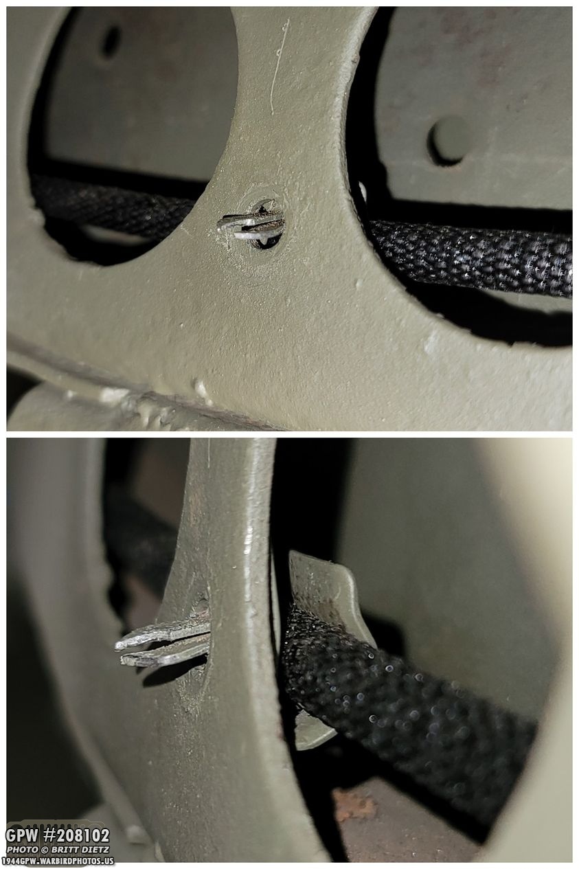
And here’s the other spot on the frame, this time showing how the clip teeth go through. A nice detail no one will know about! Ha ha.
Here I’ve screwed in the rear axle flexible line to the main hard line. Next up I need to add the brake clip to hole them in place.
It’s pretty easy to add. Just get it started at an angle, then use a hammer to tap it in. It’ll lock itself in place. This is also an original GPW clip from the Jeep.
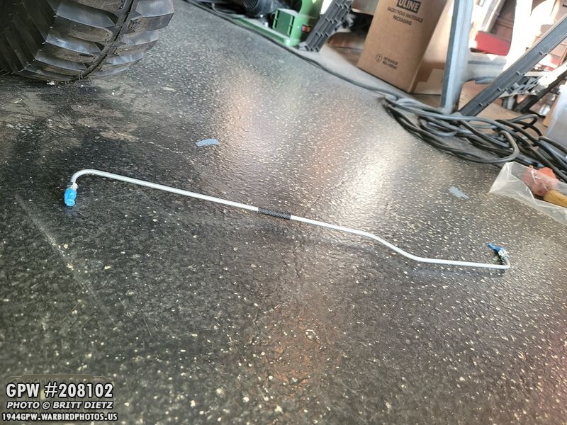
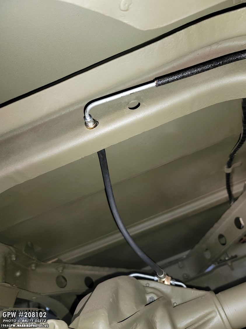
The last line to be added is the short line from the master cylinder to the front axle flexible line. I first taped the ends closed, again, to keep them free of debris.

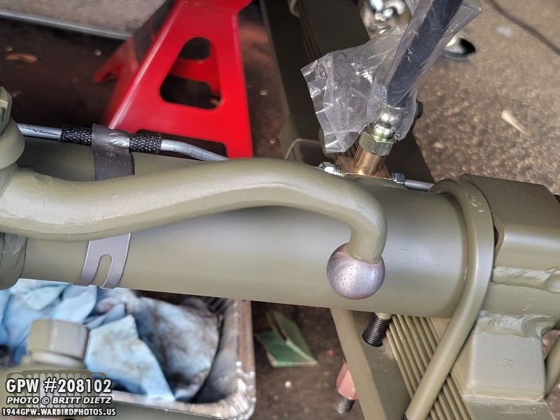
I had to look it up online, but I then realized that the large ‘hump’ in the line is for the line to go over the engine mount on the driver’s side. It then connects to the flexible line (which you can see in plastic on the left) vis the tab on the frame.

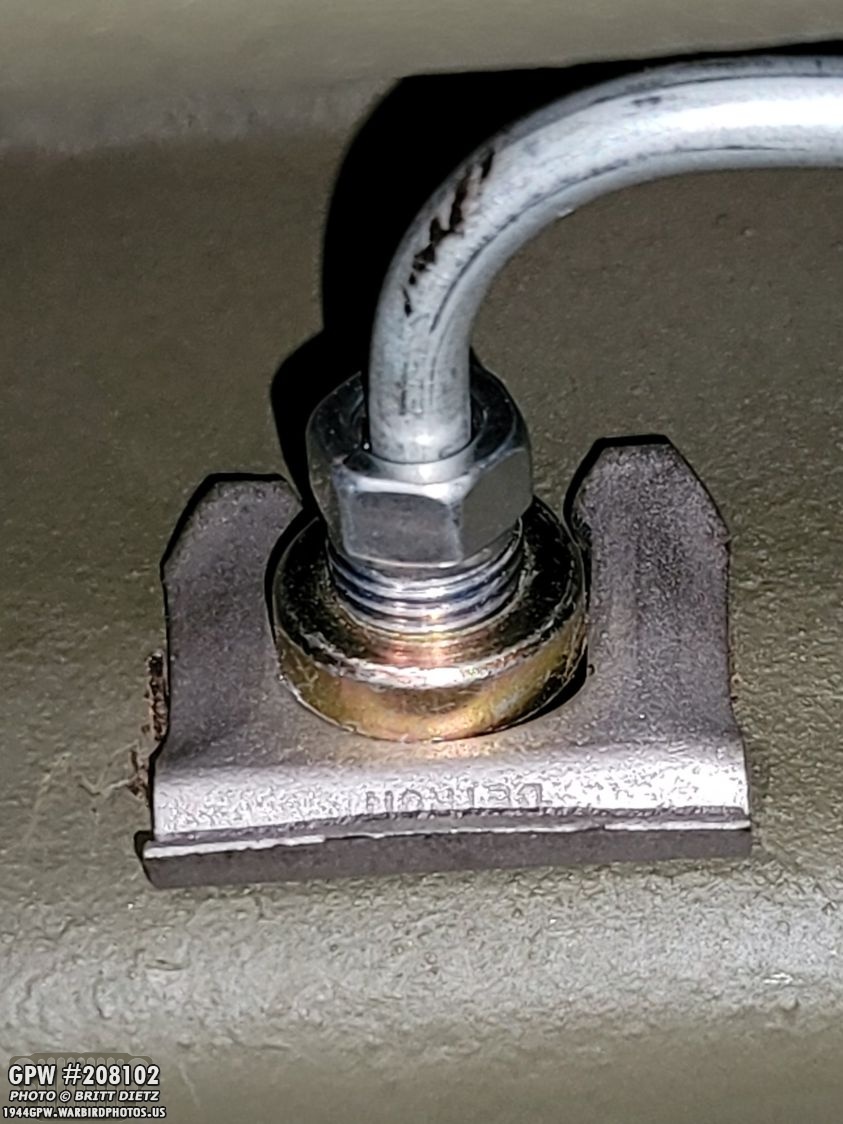
And here’s that line connected to the front axle flexible line on the tab with another brake clip. This clip was tricky to install due to the close quarters, but a small hand hammer worked well.

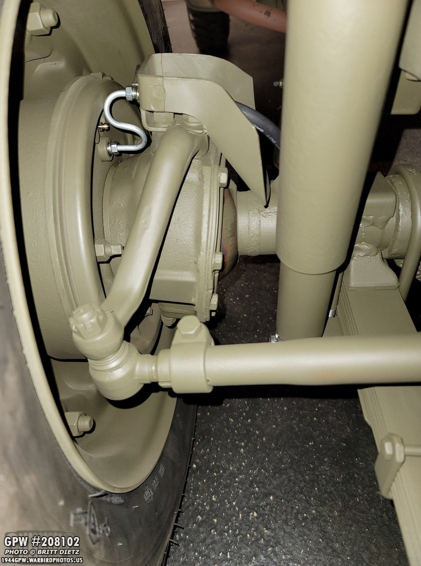
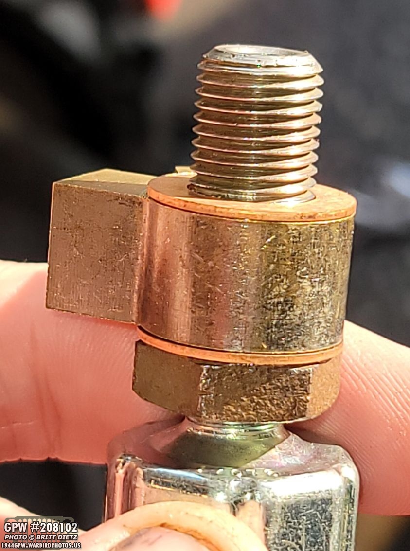
I wanted to point out to make sure you have the copper crush washers on the flexible brake lines that go to the T connectors on both the rear and front flexible lines. This is crucial for making a good seal for the brake fluid.
Moving on with the brakes, I took the master cylinder bolt, which is still connected to the brake light switch, then put on the two different copper crush washers on other side of the V connector.

And then screwed that into the freshly painted new master cylinder. I painted the master cylinder a few updates ago. I’m not going into super depth with all this as I covered this in-depth in late 2019 in an update when I replaced the original master cylinder with a new one after I found rust and corrosion in the original.

Here’s the finished master cylinder! Remember, since I’m using all new brake lines, all new master cylinders, etc… I’m using DOT 5 brake fluid instead of 3. YOU CANNOT MIX DOT 3/4 WITH 5… so ONLY do this when you are starting brand new. I went with DOT 5 as I live in SoCal, so I’m not worried about ice conditions, and I don’t want the brake fluid to mess up the paint when it gets on things.

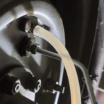
Before installing the master cylinder, I filled it with DOT 5 and pre-primed it by pumping the plunger in it until brake fluid started to squirt out of the V connector on the front. Once that happens, it’s primed. I then topped off the DOT 5 in it before screwing the lid back on.

With the last two brake lines installed, it was time to mount it on. Again, I’ve covered this in depth in an update in 2019, so I’m not going to show the entire install and all the items that are required. It’s tricky to get it installed as you have to install one bolt first while the master cylinder is facing downward, pre-install the second bolt, then rotate it up and finish screwing in the bolts. This is because one of the bolts will hit the engine block and won’t come all the way out. So pre-installing it before you rotate up the master cylinder is the only way to get it to work.
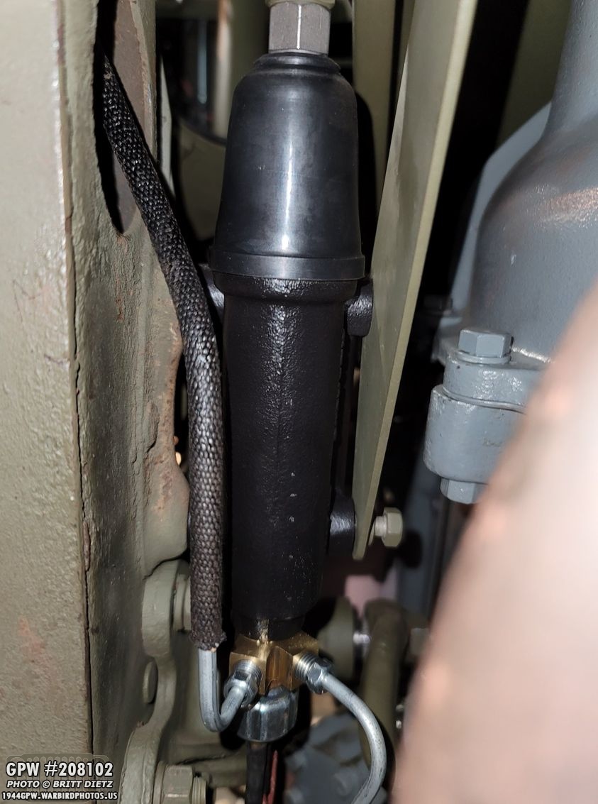
Here’s the master cylinder installed with the brake pedal mount bracket next to it!
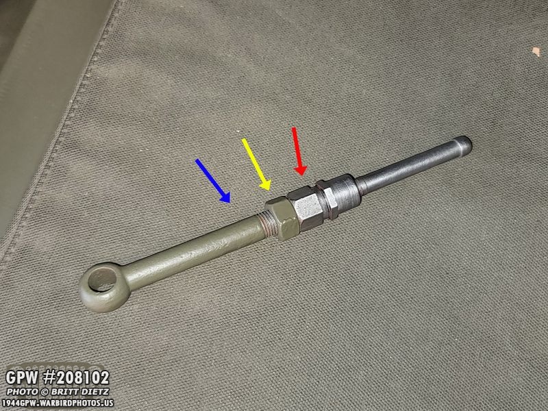
I had to readjust the plunger that pushes into the master cylinder when you press on the brake pedal. There’s three parts to a plunger… There’s the Eye side (blue), a lock nut (yellow) and the plunger (red). You unscrew the plunger side from the eye side to lengthen it, and screw in the plunger more to shorten it depending on what you need. The idea is when you have the plunder in the master cylinder and on the stud on the brake pedal, you extend it until it makes contact with the master cylinder pushing against it. You then turn it the other way to shorten it one full revolution so it’s not resting against the master cylinder. You then turn the lock nut against the plunger and it’ll lock it in place. That should give you about 1/2 inch play on the pedal.

Here’s the eye end of the plunger put through the stud on the brake pedal, with a washer and a cotter pin on the end of the stud.

And with that, it’s all installed! But, there’s no fluid in the lines… so next comes the tedious part… BRAKE BLEEDING!

Start off by taking the maintenance cover off the body tub under the driver’s side dash.

This gives you access to the master cylinder. This is how I was able to refill it with DOT 5, as once you start pumping the brake fluid by pressing the brake pedal, it’s going to empty in a hurry sending that fluid through all the lines. I used a brand new funnel with a brand new tube (DO NOT GET ANY FOREIGN DEBRIS IN THE FLUID!) to refill the master cylinder. I had someone else pour it as I held the tube and watched, with a flashlight, into the master cylinder so it wouldn’t overflow. Overall, we had to refill it about 4 times during the entire process. Twice as it was pumping fluid through the lines, and then twice as I was bleeding the individual wheels. It’s good to periodically check the level.
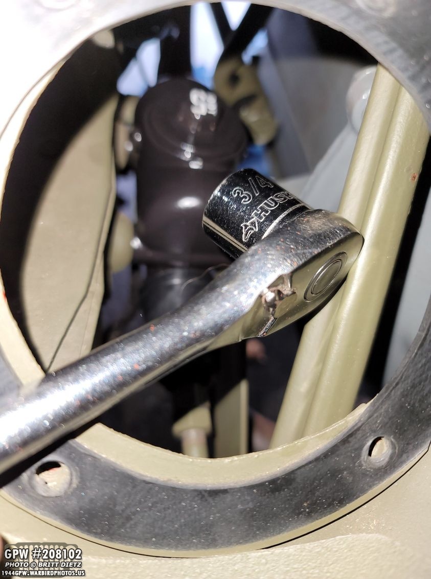
To open the lid, take a 3/4 socket and a rachet and you can open/close it through that maintenance hole in the body.

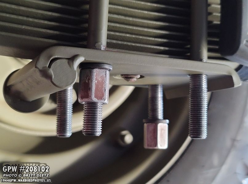
Before I started the bleeding, I took one of these special wrenches and using the 3/8 side, I tightened the HECK out of all the brake line connectors.

I had some spots that were leaking (thank goodness I used DOT 5! no paint damage and easy clean up), so I tightened them REALLY tight, which stopped all leaks.
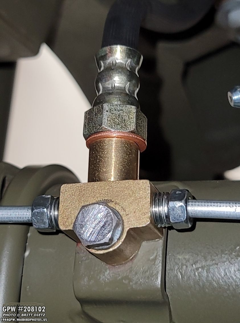
This front T connector had a good size leak, but after tightening it to the point I couldn’t move it stopped the leak completely! So double-check all the fittings.

To bleed the brakes, you need to start at the furthest away spot, which is the passenger rear wheel, and go wheel by wheel doing the next further away wheel. Here’s the order you should use.

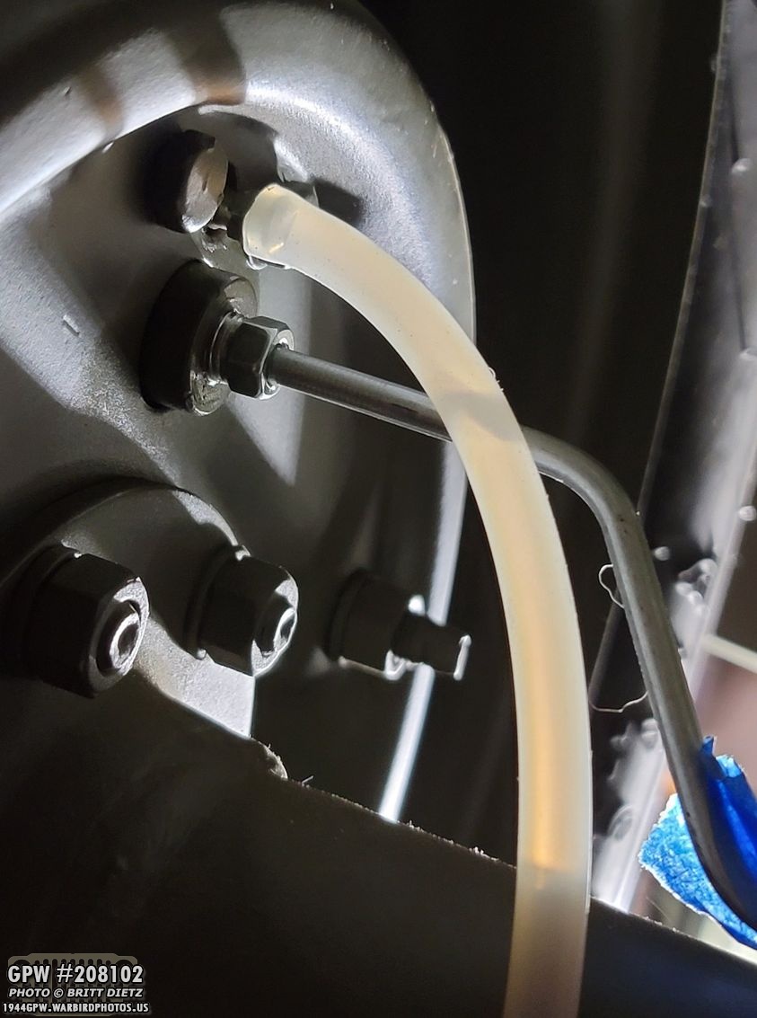
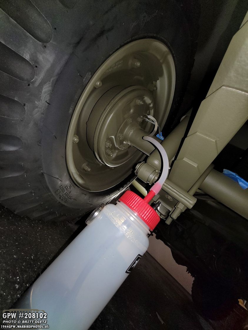
So, how do you bleed brakes? It’s pretty simple and with two people it’s easy. Get a brake bleeding kit, as shown here. You just need the tube, and the container to capture the brake fluid as it comes out. You put the tube on the end of the brake bleeder nozzle on the back of the wheel, then turn that nozzle counterclockwise to open it up. Have someone get in the Jeep, and have them lightly start tapping on the brake. You should see the fluid come out of the nozzle, down the tube, and into the container. The container should have a one-way valve, so it can’t go back up into the nozzle. Note – In this photo I’m doing the second to last wheel.
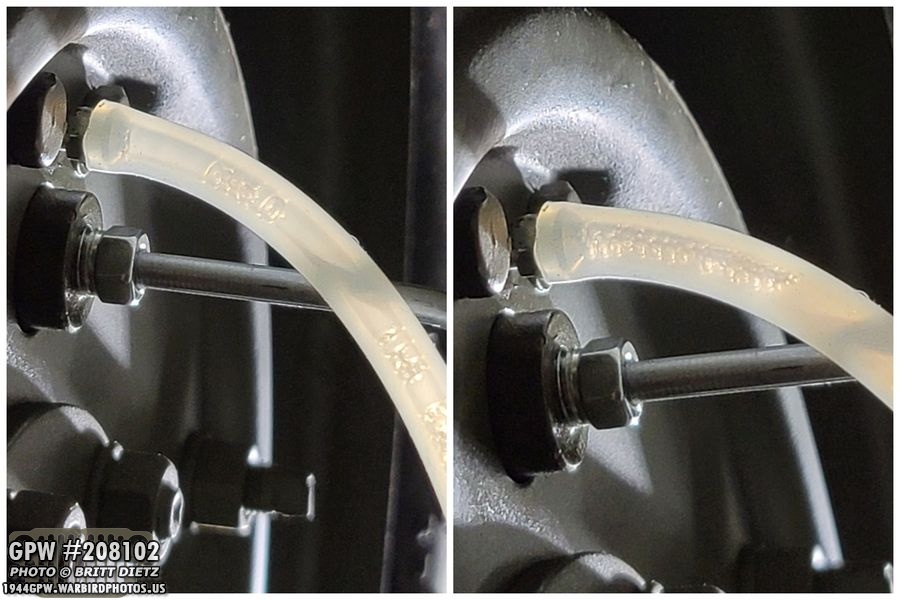
This is what you’re looking for, or looking to NOT see. Bubbles! When you see bubbles coming out as the person in the Jeep lightly pumps the brakes, then it’s not bled and there’s air in the system. Continue pumping the brakes until you can’t see any bubbles coming out. They can fool you, sometimes they will appear to be done, but then wait a second without pumping the brake pedal, and you’ll see a train of them suddenly come out.
THIS is what you want to see. NO bubbles! Once you have pumped the brakes a few times and no more bubbles come out, turn that nozzle clockwise to close it, then pull off the tube. Bleeding is done on that wheel! Move to the next one.
Once you’ve gone through all wheels and there’s no bubbles (remember to periodically check the master cylinder brake fluid level! If it goes empty, you could introduce air back into the system), I recommend starting over and going back to the furthest one and checking it again. This is an important part of safety on the Jeep, not worth risking. For me, when I went through it the second time there were no bubbles, telling me I did a good job the first time. So the second time went super quick.
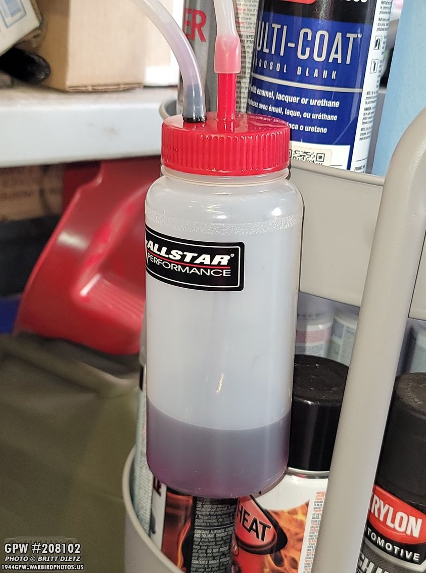
Since it was a brand new brake system, I wasted a LOT of brake fluid, so be prepared to get more than you need. Even though this doesn’t look like much, this was JUST the fluid that came out during the second round of checking the bleeding! I had to empty this container as the first round filled it almost completely.
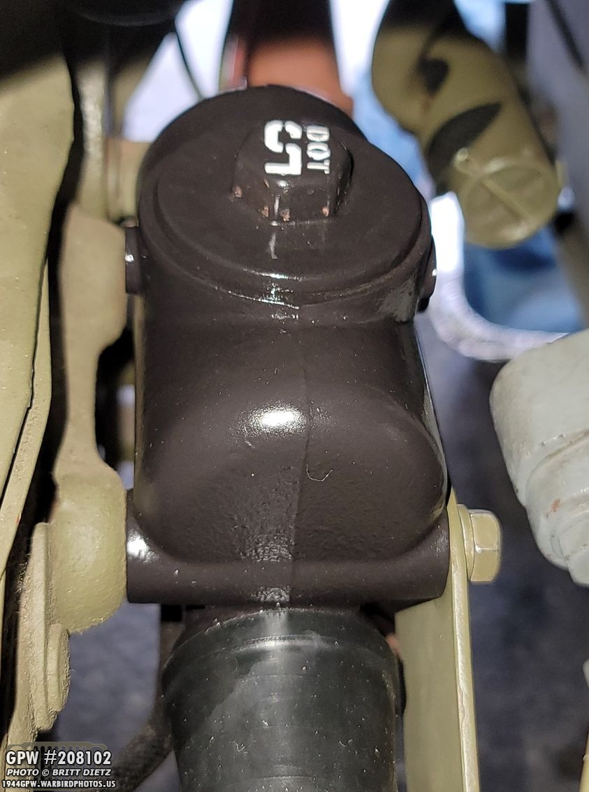
With that, you are DONE bleeding the brakes! Top off the fluid levels in the master cylinder (make it just under the start of the threads for the cap, maybe a 1/2 inch gap) then tighten the cap. ALL DONE! If you do use DOT 5, it’s a good idea to label that on the cap, as I’ve done, so you and anyone else know for certain NOT to put in DOT 3/4.

After that, you can put on the maintenance cover plate back on. I have been using a repro one, but I had a tough about using my original one. I didn’t originally as the holes didn’t line up. But I wanted to see if I could make it work. Repro top, original F stamped bottom.

Overlaying the repro on top of the original, you can see how the holes don’t align. I decided to see if I could finagle the bolts to work.

And I was able to! Using the correct recessed head bolts that I research earlier last year, I was able to get it all lined up, barely. Nice to have another original item back on the Jeep!

So, what’s next? Well… reinstalling the drive shafts and then taking it out for a test spin!! But that’ll be in next week’s update… including good/bad news! But, it’s exciting to be rid of those CJ axles and steering system and have actual original GPW axles and steering items back on the Jeep! Plus a brand new braking system!

I also wanted to point out the F stamps on the U bolts… a nice detail to add. On the right photo, after I took it I noticed the paint scuffs and then (after masking off the brake lines) touched up the OD Green paint.

And with that, this week’s update is at an end! Look for lots more next week! Till next week…