 Small projects, custom F Stamps, Hood work, and completing the rear axle!
This past week was a flurry of work on the Jeep in prep for the Veterans Day military vehicle and car show in Old Town Tustin, CA. That meant finishing some smaller projects that I’d been meaning to get around to (mostly cosmetic things). Some photos from the Veterans Day event and the 9 other Jeeps that showed up included. I continued work on the GPW hood and had a major setback. And I FINALLY finished the rear GPW axle! Work then began on the Front axle

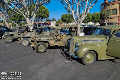
Here’s the Jeep out at the Veterans Day event on Wednesday (center Jeep). It was in good company with many other military vehicles including 9 other Jeeps! My Jeep is parted between two MBs and a beautiful Plymouth Staff Car. More on the event later. Let’s move on!

Last week, I talked about how my Jeep has had M38 (Korean War era Jeep) axle shock bumpers. These are attached to the frame and stop the axle from crashing into the frame when going over large rocks. The top photo shows the difference, with the primer painted correct WW2 square style and one of the pointed round M38s that were on my Jeep. I primed and painted the four correct ones last week.

After removing the first two M38 bumpers, I realized the bolts were in pretty bad shape. Rather than take a lot of time to restore the bolts (they look post-war anyway), I just went out and got brand new bolts.

I tested the new WW2 style bumpers on the frame to make sure the fit was good, and they fit perfectly! What’s interesting to note is the rear bumpers are just holes in the frame to attach them. So you need a bolt, washer, lock washer, and nut.

Both the rear bumpers are installed and the paint touched up.

The front bumpers, however, are harder to get to so they have capture nuts welded to the frame. I wasn’t expecting that, but once I got to them and realized I could get my hand or wrench in there to search for a nut, I realized they must be capture nuts. These bolts did NOT want to cooperate, and they took a lot of work to get off. But once off, it’s clear these bumpers have been on here for a long time. I took some sand paper and cleaned up the surface rust (shown here after sanding).

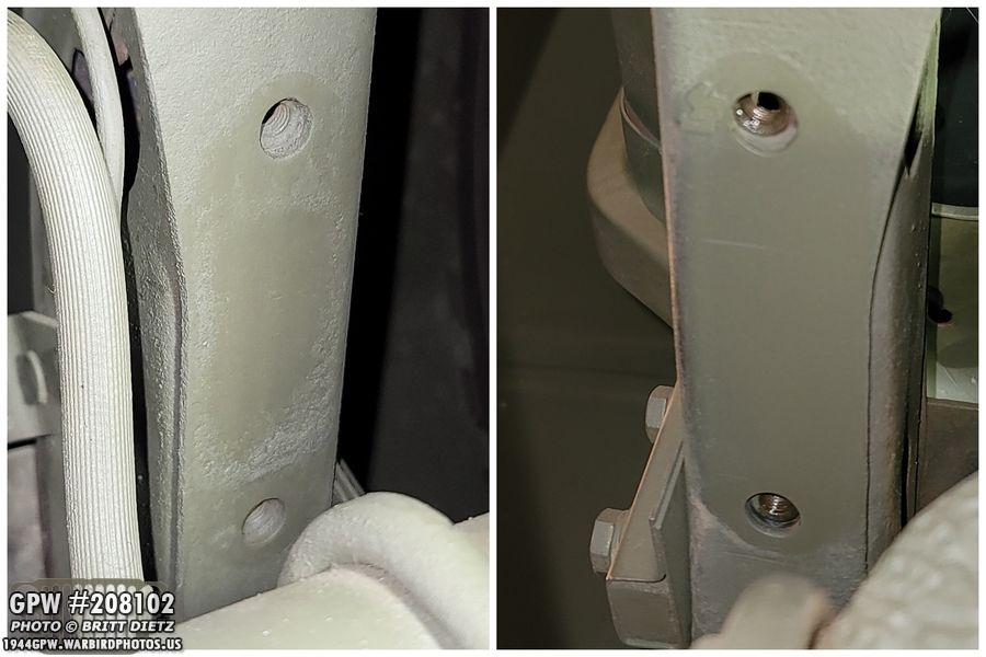
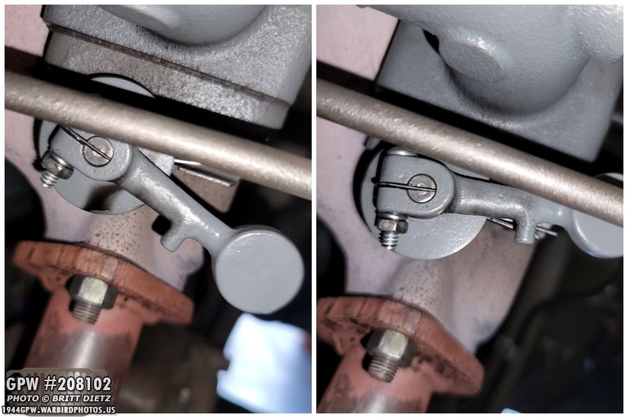
The other front bumper, on the driver’s side, was a pain. Both bolts did NOT want to come out. They fought me EVERY SINGLE TURN or the rachet. Underneath it was rather rusty (left photo). After some sanding, it looked a lot better (right photo).
Once I cleaned them up, I hit them with some paint on the frame to make sure no metal was exposed. Judging by the amount of surface rust, I imagine moisture gets trapped in the area between the bumpers and the frame.

As the paint dried on the frame, I decided to tackle the capture nut threads. Even though I was going to be using new bolts, I wanted to make those threads as clean and sharp as possible.

Using a tap with some oil, I slowly cut the threads back to being clean. The spacing in that area is so tight, I can’t use a handle at all, so I had to screw it in like this. It was quite the task. But, I eventually managed to get all four capture nuts freshly cut with good thread.

After tapping the threads, the new bolts went in like butter! Here’s both the front bumpers all installed. Since it’s a capture nut, the lock washer is on the outside with the bolt head. After this photo, I touched up the paint on the bolts, and all four were now installed! Nice to have correct style bumpers back on the Jeep!
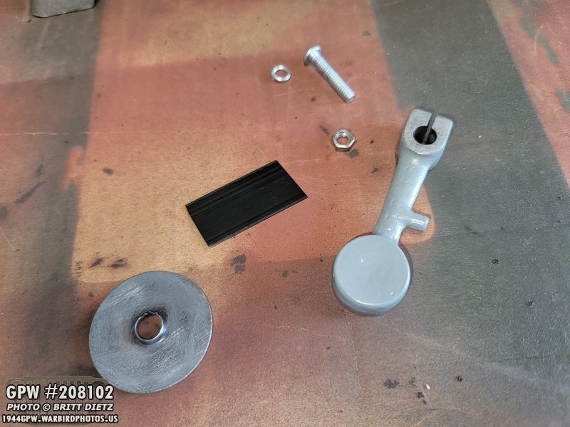
Last week after Hallowen night when I had the Jeep on display outside for tick or treators, I took the Jeep up the street and back before putting in the garage. As I was making a turn to come back to the house, I heard this loud clanging noises and the sound of parts hitting the street. Oh no… I quickly pulled over and saw that all my heat riser parts on the manifold had come off and scattered all over the street. UGH. I was able to find the ‘lollipop’ weight and the large washer (shown here), but the spring, screw with nut, and the little insert tab in the lollipop weight were missing. We looked all over the street for it, but we couldn’t find them. So I went about the next day finding a correct style screw, this time with a lock washer, as I think the nut vibrated off making the lollipop weight fall off, and the other items went after. I could get another spring, but the little tab piece I would need to make myself.

And in last week’s update, I showed this set of items that arrived from &Ron Fitzpatrick Jeep Parts, and one of the items, you can see, is a new spring.

Making the little tab was actually quite easy. I used some metal binding wire, cut it to size and rounded the edges (top two photos). Fitting it in the slot on the lollipop weight, it was a perfect fit. After that, I just drilled the correct size hole and now I have a replacement! This tab holds the lollipop weight to the slotted rod on the manifold.
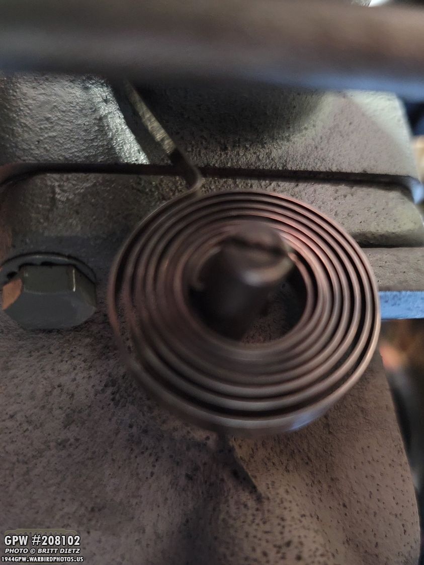
Putting the spring on the heat riser rod on the side of the manifold, I instantly realized something was wrong.
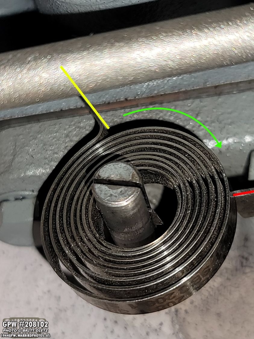
There’s only two ways this can go on (technically four ways, but since the spring moves in the direction of the green arrow when heated, it’s only with the outer ring travelling clock-wise that is correct). So in this position, the tab on the spring is in the top 11 position (yellow line). That yellow line should be resing on the tab bracket that’s on the manifold (red line). So this way isn’t right, as the spring tab would have to travel from the 11 position to the 3 position when heated as the spring expands till it starts to turn that rod once it hits that red line.

So putting the spring on the other way (see that slot on the rod? There’s an inner tab on the spring that slides into that tab). In this position, the spring tab is in the 5 position, and way past the red line where the manifold tab is. This is definitely wrong. I consulted with Roger Smith, who said I might need to either trim the spring or take a look at how it’s coiled. That gave me an idea.

I used my long needle-nosed pliers to hold onto that tab in the middle of the spring, and I tightly wound the spring tighter. It held its shape the tighter I wound it. Will that make it work?

YES! It took a few tries of winding it a bit tighter and slightly unwinding it, but I eventually got it to be right where it needed to be, shown here. It should be resting on the tab, so the second it starts to heat up and expand, it turns the center rod causing the weight to go up and, in turn, close the heat flapper inside the manifold sending the hot exhaust out to the exhaust pipe instead of back into the manifold to warm up the engine faster.
The real test was putting it all together and heating it up. The first image shows the spring, washer, lollipop weight, and the custom made tab installed with the screw, lock washer, and nut (that isn’t coming off this time!). I then used a small lighter under the spring to heat it up. Sure enough, it started to raise the lollipop (right photo)! Checking on it later when I was actually running the engine, it went all the way into the closed position!

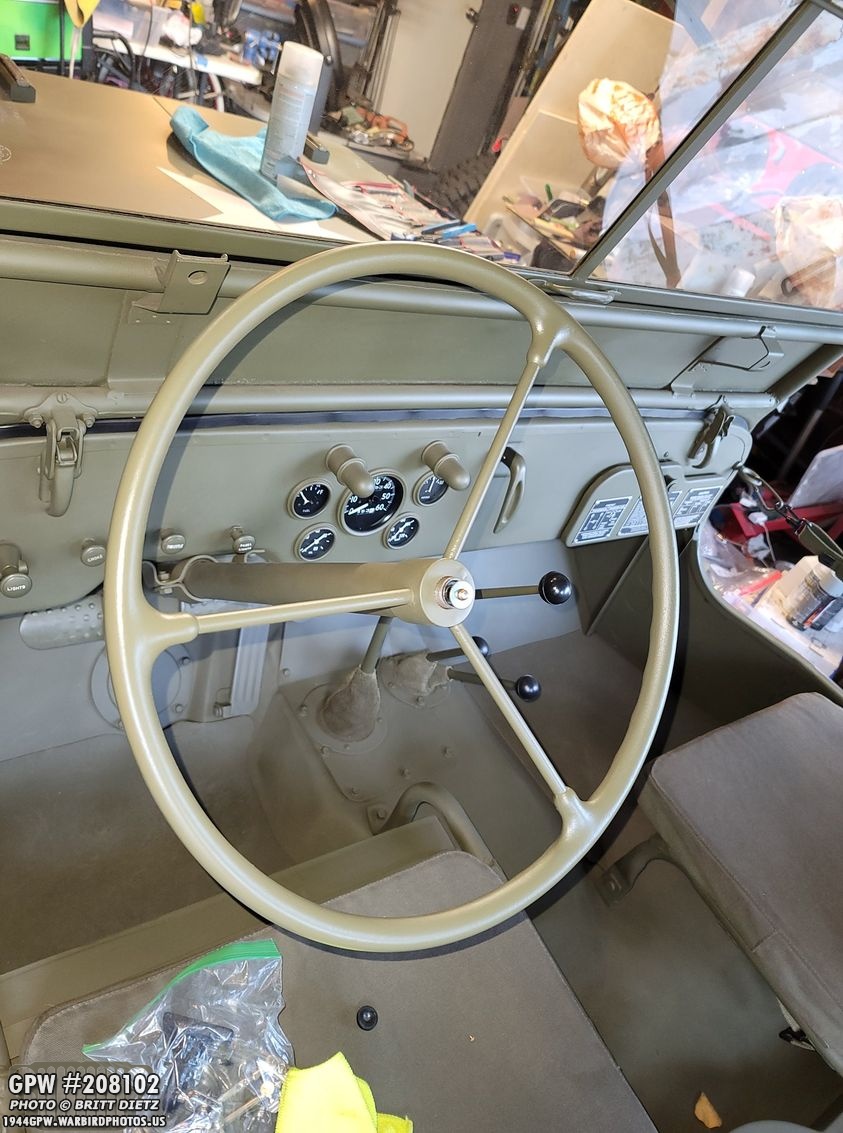
Moving on, I had some other items on the Jeep that needed some work before the Veterans Day event. Shown here, I needed to do some touch up work on the steering wheel, which I removed from the Jeep, along with the battery splash shield (to the left of the steering wheel). And here’s a preview look at the front axle which is now on the work bench!

The steering wheel had been losing some paint from my driving the Jeep in some high wear areas where my hands are. I decided to repaint the whole wheel.
Sadly, I didn’t take any photos of the process as I had multiple projects going on at the same time. But I sanded the entire wheel, cleaned it really well, reprimed any areas that got to the metal, and then put 2 coats of 33070 OD Green. After it was all dry, I put two coats of Rustoleum Matte Clear over-spray over the OD Green to help lock in the paint and hopefully slow down the wearing of the paint.

The battery tray has been through a lot over the years. When I originally restored this battery splash tray, I didn’t do too much to fix it. It’s original to my Jeep, and it appears someone fixed a crack at some point with some welding but never ground down the welds. The tray has some buckles in it, and it’s pitted. But overall, it does what it needs to do. Since I put paint back on it after cleaning it up, it’s had fuel leaks, scratches, all sorts of things. So I’ve been meaning to take it out and clean it up, fix that weld, and repaint it.

And it’s hard to see when painted, so I sanded the paint a bit, you can see GPW and a partial F stamp underneath through the pitting. An original item!
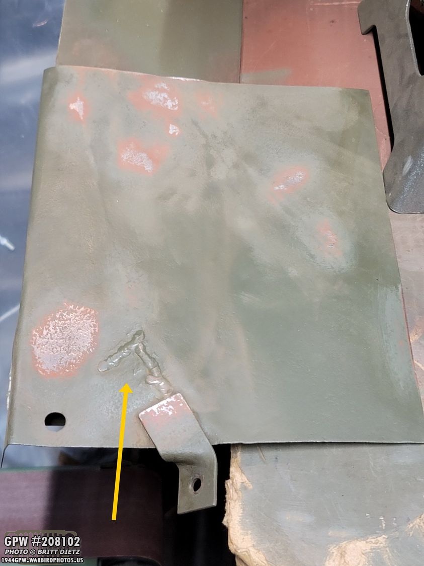
I first sanded the tray, sanding the paint around all the scratches. The yellow arrow is pointing towards the weld that I need to ground down.

Grinding the weld down took more time than I thought. As I was using the flap disk, the crack reappeared, so I think the welding wasn’t strong enough to penetrate into the crack everywhere. I had to reweld it myself and regrind it again.

After a lot of work, I got it looking much better, and touched up the red oxide primer paint before hitting it with the 33070 OD Green. I tried to flatten the buckles, but in doing so I noticed some cracks forming, so I stopped doing that, repaired the cracks, and decided it was good as is.

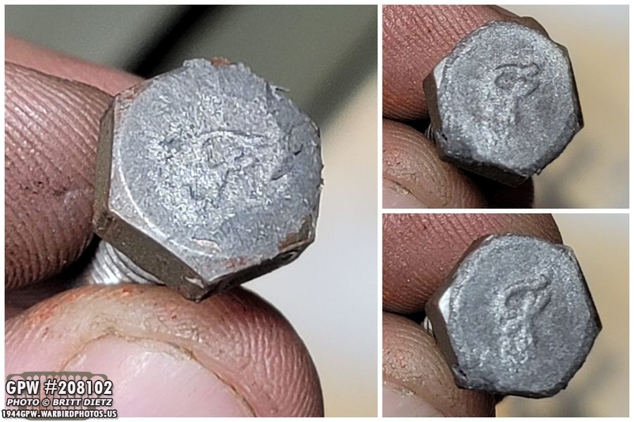
Since you can technically see one of the bolts when looking in the engine bay, I originally thought about maybe sourcing some F stamped bolts. The bolts I had put on there had modern heads, so I at least ground those down flat. But then I remembered, I had read about someone on G503 making their own F stamp bolts! I figured this might be a good time to try that out. Here’s how it works… first, you start with a blob of JB Weld Steel. You mix it well, then flatten it so it’s flat on both sides. You then take an F marked bolt, and press it in to the blobs. I started off with these two where I pressed them in a little hard so the top of the bolt also pressed in.

I ended up doing two more, with different F styles and also one with just only the F pressed in. You let them harden for 24 hours, and they are ready to use! To keep from what you put in these F molds from sticking to the mold, you need to put something that will release the material. A silicone release would work well, but I didn’t have that. So I tried some spray paint, that didn’t work. What did work was using some Permatex anti-seize paste.

Now, take your bolt… make sure the head is super clean and take rough sandpaper to scratch up the head to give the next part something to hold on to.
Take a tiny bit JB Weld steel (a very tiny bit), press it on the head of the bolt, and press the bolt into the mold with the anti-seize on it. Slowly take out the bolt (and hopefully the JB weld with it). These are not perfect, but that’s great since real F bolts won’t look perfect.

After they are hardened 24 hours later, use sand paper to clean the edges of the JB weld so it’s a smooth transition. Then paint away!

Here’s a look at one of the first ones I did. Not perfect, but it looks the part!
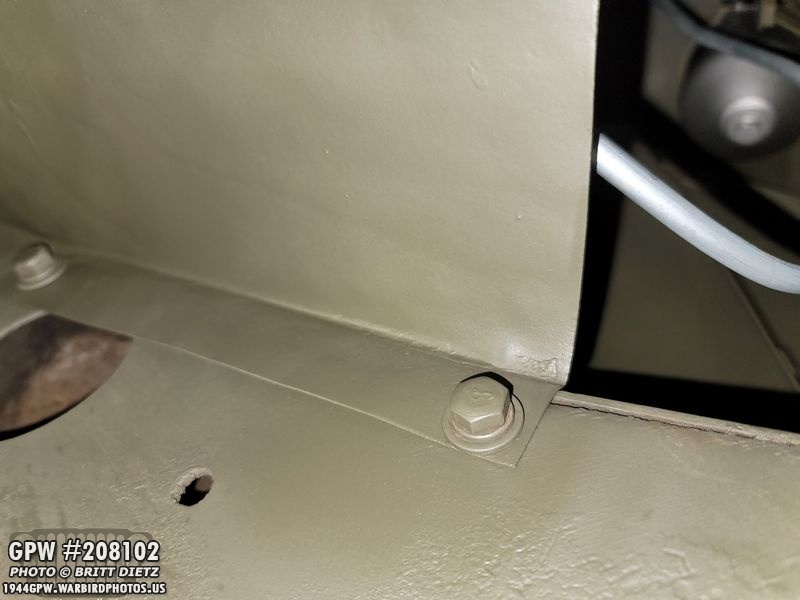
I ended up doing this process to the three bolts that hold the battery splash tray to the frame! Here’s a look at the first one. These came out a ton better.

And here’s the other two! I still need to touch up the paint after I scratched them a bit while tightening them, but now I have ‘F Bolts’ that really didn’t cost me anything but my time!

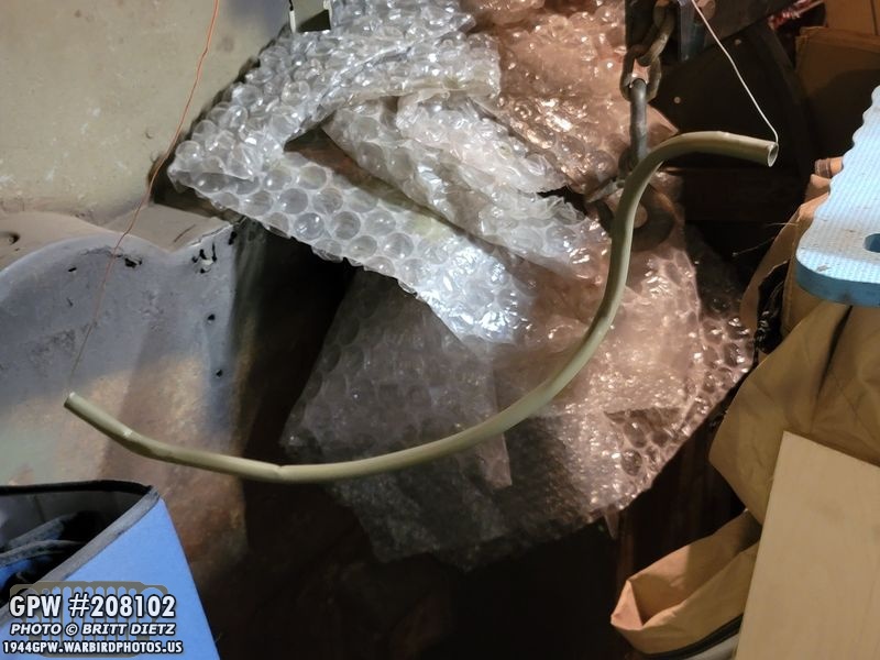
When I was having issues with the radiator overflowing through the overflow tube, it would drip on the axle causing a mess and staining the paint. So, someone mentioned putting a hose on the radiator overflow tube to ‘extend it’ past the axle so it just drips on the ground. Genius! so I had a piece of tubing with a flexible wire taped on crudely so I could straighten out the curled tubing and bend it away from the axle. It looked terrible, and I wanted something more hidden and, at the very least, better. So I found some thin metal tubing used for washer tubing. I was able to carefully bend it into a custom shape.

I roughed up the metal and used red oxide primer.
I then painted it 33070 OD Green.
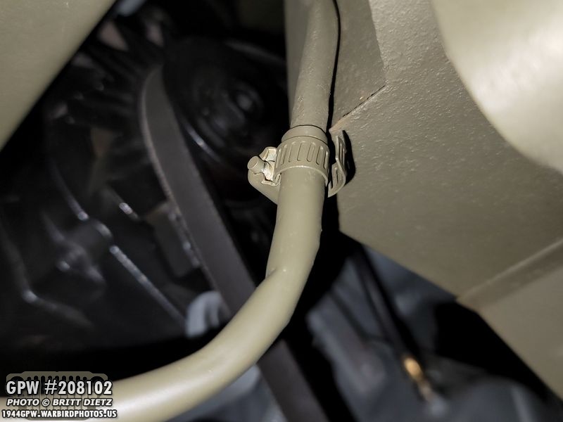
Once dry, I used a small hose clip (painted the same 33070) and clamped it to the end of the radiator overflow tube.

To keep the metal tube from getting caught up or hit by the axle, I bent the line so it goes into the passenger side engine mount and comes out the other side under the battery splasy shield tray (which I hadn’t reinstalled yet at that point). This will keep any drips off the axle, especially when I put the newly restored GPW axles on my Jeep with the brand new paint job, and it hides pretty well. Win-win!

The night before the Veterans Day event, I was crazy busy getting the Jeep all cleaned. I cleaned the windows (shown here) and did a cleaning of the entire outside of the Jeep and in the wheel wells. I also blew out any leaves or dust inside the Jeep. She was ready to go!

I also knew I’d be driving around the area, so I made myself a ‘extras’ bag with two screw type tire valve caps, a spare Firestone F-40 1942 dated spark plug along with a modern spark plug. I also have a spare LED light for the brake light in the unlikely case the other one dies. This bag will stay with my Jeep along with the tool roll I have with various wrenches, screwdrivers, rachets, carburetor tools, etc

And with that, she was ready to shine in only the SECOND event she’ll have ever been to (this was supposed to be the big year where I take her to all sorts of events, but COVID happened).
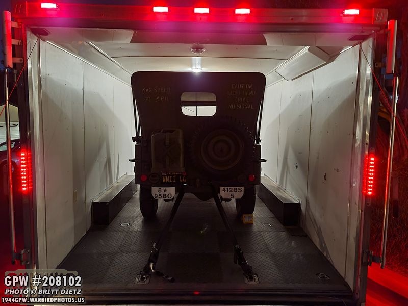
I was fortunate enough to borrow the massive enclosed trailer again, which can almost fit two Jeeps. I’m spoiled, as I don’t have to take down the canvas top and windshield (which is a must if you’re transporting a Jeep on an open-air trailer as the windshield was not designed to go past 55-60mph).

And here’s the Jeep out at the event before the classic cars started to arrive! It’s tough to see in this photo, but there’s two Jeeps ahead of mine, two staff cars, and seven more Jeeps in front and on either side of the blue tent.
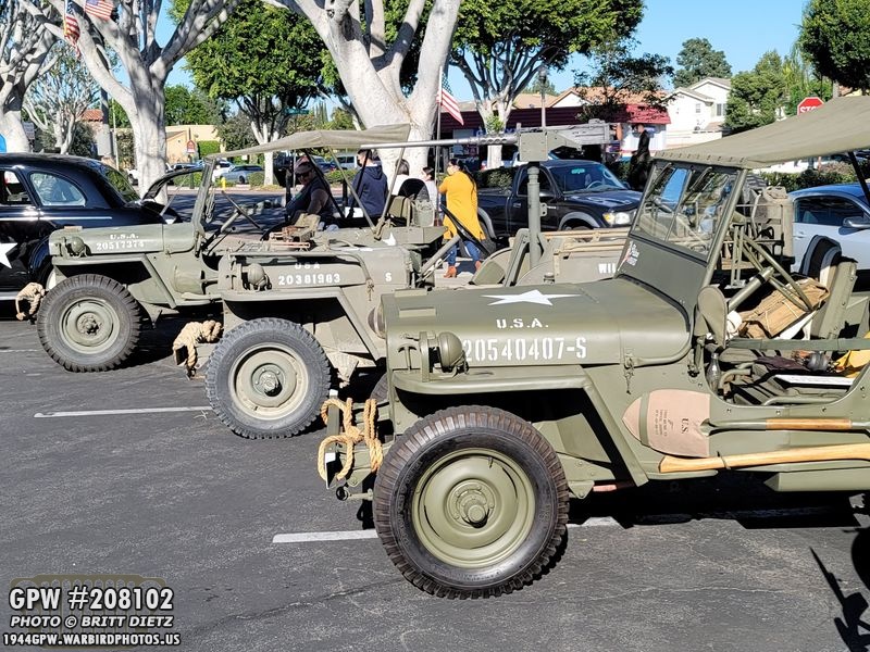
I ended up moving my Jeep next to two other Jeeps, the one next to mine with the .50 cal is a friend of mines. The first time the two Jeeps have been together since my full restoration.
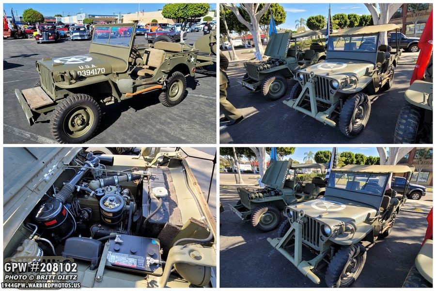
Here’s a look at some of the other Jeeps at the event! Most were owned by one person! They were an oddball assortment of MB and GPW Jeeps. (sorry, didn’t realize the right two images are the same two Jeeps)

And here’s some of the other Jeeps, including two USMC Jeeps on the bottom two photos. It was a great event with somewhere around 70 or more classic cars that attended! Great turn out by the military vehicles and the classic cars to celebrate the veterans!

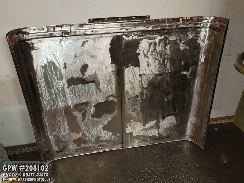
Now on to other projects, this week I continued work on the Hood. Here’s the last patch of the inside of the hood that I still needed to wire wheel. It’s a long, messy, tiring process wire wheeling it yourself (wear a respirator!), but you do feel accomplished when you start to see more metal than rusted 75-year-old paint.

I noticed two more stress micro-cracks which I quickly welded (shown) and then ground down smooth as if they were never there! It’s nice to do these small fixes with the welder.

And here’s the inside of the hood ALL metal, FINALLY! The other side still has paint to remove, but it was a huge accomplishment to get all the paint off the inside!
I ended up using some JB Weld and Bondo to help fill some areas where the rust had made some holes. This is where I made my big mistake. As I was sanding the JB Weld Steel and Bondo, I had the hood propped up against the garage door, as shown here. I should have moved it back to the table… I forgot it was there, and the next day I walked into the garage and opened the garage door, as I normally do… to the incredibly loud BAM sound of the hood falling over and hitting the concrete hard. UGH.

And that hit cracked the weld work I’d just done trying to fix this area where the two hat channels come together. UGH! The crack reappeared and my weld spots broke. I know what you’re saying, those must have been poor weld spots. Well, the metal in this area is so thin, it blows through like tissue paper even at the lowest settings on the welder. I attached it in places that I could the best I could, and used JB Weld Steel to fill the gaps. Plus, unless I slam the hood down when it’s on the Jeep, it would never have a shock that hard as it did falling over.

I spent the better part of an hour slowly attacking this area trying to build up the metal. I would start in an area I could get the weld to stick, then I would use that to slowly built it outwards. The metal would often blow out like nothing, so I’d have to continue building, stopping to let it cool, building more, stopping again, etc until it would get a spot of metal it could hold on to on the other side, then I’d go the other ways until I filled all the holes. It was a long slow process. It’s not pretty by any respects, but it’s a much stronger weld now and it feels REALLY solid.

After grinding it down smooth as I could with a flap wheel, cut off wheel, dremel with various tools, and the drill with various tools… I got it looking as smooth as possible. There were some areas that were VERY hard to get any grinding tools into, so they are not perfect. But I put some more JB Weld Steel on (using it like Bondo) to smooth out the grinding. I applied this Thursday (yesterday), so look for the final results next week.

To help keep the hood in the proper shape (and also have the outer curved edges curve in better), I have a rachet on the hood to help pull the sides in. I used my torch to lightly heat up the metal around the curves to better keep the shape. That’s it for the hood this week, look for more next week!
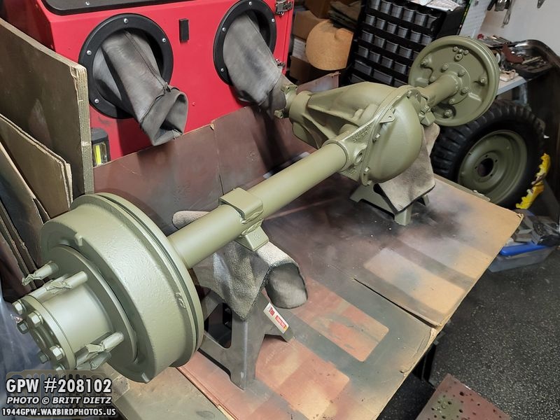
Moving on to the axles! Here’s how the rear axle looked last week after the final paint job and installation.

A few updates ago, I test fitted the brake lines adding the various parts to the axle (minus the cover clip, which I had to steal from the CJ rear axle on my jeep currently).
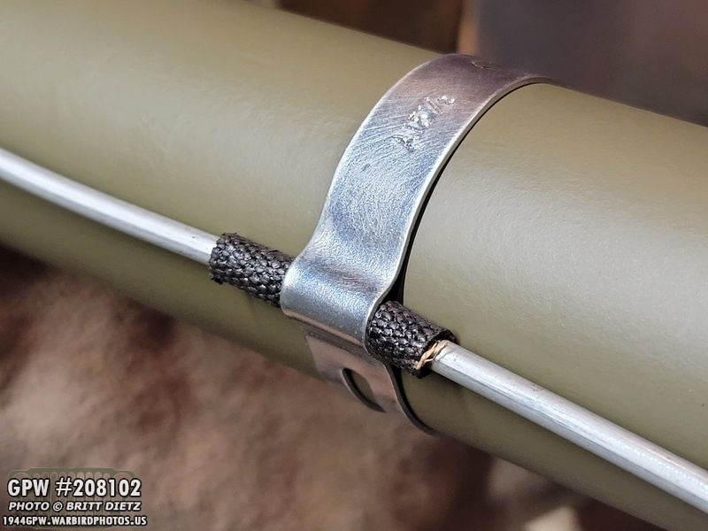
Here’s a look at that clip from the CJ axle, after I cleaned it up and added it to the rear axle brake line.

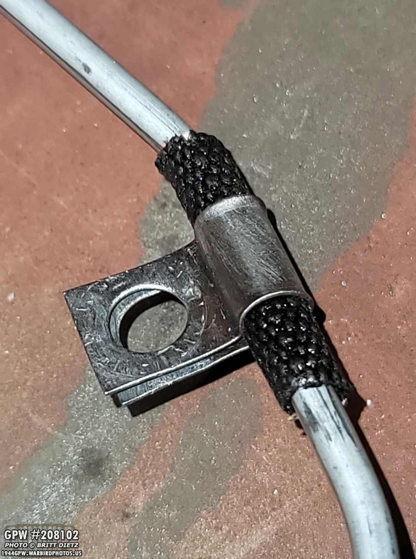
I bought another strap for the rear axle. I’ve only seen it listed with one clip on the rear axle, but there were two spots of the asphalt loom on the brake line, and it was recommended to have a clip on both sides. So I got the clip and, like the other one, bent a notch in it to better hold onto the line.
Here’s a look at the other side clip that I bent the notch into.

Adding the 3-way connector, the left and right brake lines, and the rubber brake hose was very easy!

Here’s the clip added to the differential cover bolt holding the line. It, along with the other metal hardware (but not the brake lines) were coated with an anti-rust clear coat.

Here’s a look at the cover with everything installed!

And there we go, with that… the rear axle is finally DONE! I still need to add gear oil to it before using it, but I’m considering it finished! It’s been a LONG journey, almost an entire year!
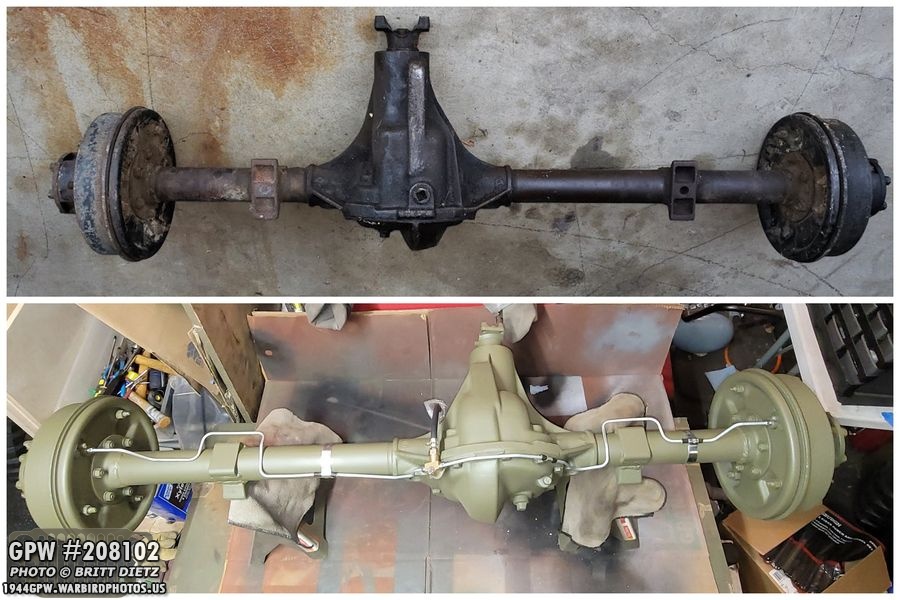
Sadly, I never took a photo of the rear axle when I first got it showing the whole axle. I regret that. But here’s a photo of the bottom of the rear axle that I was sent from the gentleman who gave me the axles. So this will have to do for a before-after photo. The rear axle has been through a lot these past 11 months. From the full tear apart, realizing the insides were damaged from a spider gear explosion causing me to not be able to use the ring, pinion, and carrier, having to source NOS or take-offs of all those items, several delaying issues with bearings, deep cleaning the entire axle caked with 75 years of grime, fixing the crack in the housing from the gear explosion, repainting the axle, redoing the brakes, all the way to final painting and installation of the brake lines!

It occurred to me that I’m pretty sure that I had the brake drums on the correct sides, but the studs have been masked off with tape for months now as I’ve painted the drums. So I popped some of the tape off, and whew, I did get them correct! The ends of the studs are marked with what way the thread goes. The general rule is the driver’s side should have right-hand thread and the passenger side should have left-hand thread.

With the rear axle done, I jumped right into the front axle (shown here from a few months ago when I was painting it) which I knew will be much more difficult to put together with the whole steering system.

I decided to use the TM manual that includes the instructions for reassembling the axles to start me off. The first project, the bell crank shaft! I installed the shaft into the axle earlier this year and added the tapered pin to keep it in place. I put in a new shaft as the original had a slight wear section on it. Here I’ve added the original washer to start the process.

Next, I added some grease to the shaft where the bell crank will go.

Here’s the bell crank on the shaft. I’ve already replaced the two internal bearings and the rubber seals in the bell crank earlier this year.
Here’s a look at it so far! The new bearings make that bell crank turn nice and smooth! I added some very slight grease on the top of the bell crank where it will rub against the next item…

Next up, the tabbed washer that fits into the groove on the shaft.

Next item is the dust shield. I used the original F stamped dust shield that I cleaned up.

Dust shield on the shaft.
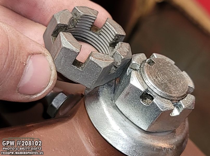
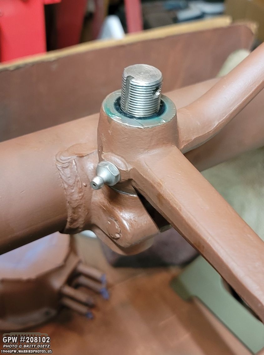
Next is to add the crown nut. I first used the new nut that I had gotten in the kit with the new shaft, but I realized that the repro crown nut wasn’t going to work! The slots going vertically down the sides of the nut weren’t deep enough to fully allow a cotter pin to go through. So I went back into my bag and got out the original crown nut, which (as you can see) has much deeper slots.

That worked perfectly. To tighten this nut, you get it to where it’s tight, it can still spin with some resistance, and the slots are lined up with the hole for the cotter pin. You then back it off ONE TOOTH, or counterclockwise till the cotter pin hole lines up with the previous slot. That should make the arm pretty loose, but not so lose it wobbles up and down. Insert cotter pin and bend it over. And that’s it! Done with the bell crank!

So that’s it for this week! Here’s another shot from the Veterans Day event with the standard ‘rear’ shot I do of my Jeep along with the other Jeeps at the event. Next week I plan on working more with the Hood, continuing the front axle work (hopefully getting over halfway done reassembling it), and another ‘detail’ project I’ll reveal then! Till next week…