 Rear Axle Extravaganza Continues!
This past week I attempted to finish putting back together with the rear axle with the springs and leaf plates but ran into huge setbacks. After a few failed attempts, I shifted focus from the rear to the starting process of removing the front springs, shocks, and axle.
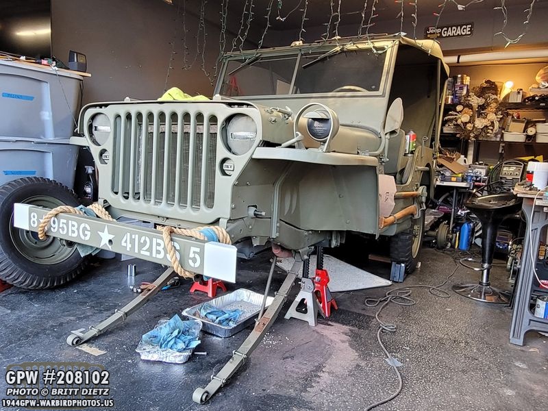
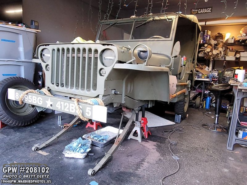
Hope everyone had a nice Christmas! The Jeep is missing something… can’t quite figure out what. Oh yes, a front axle! We’ll get to this in a bit.

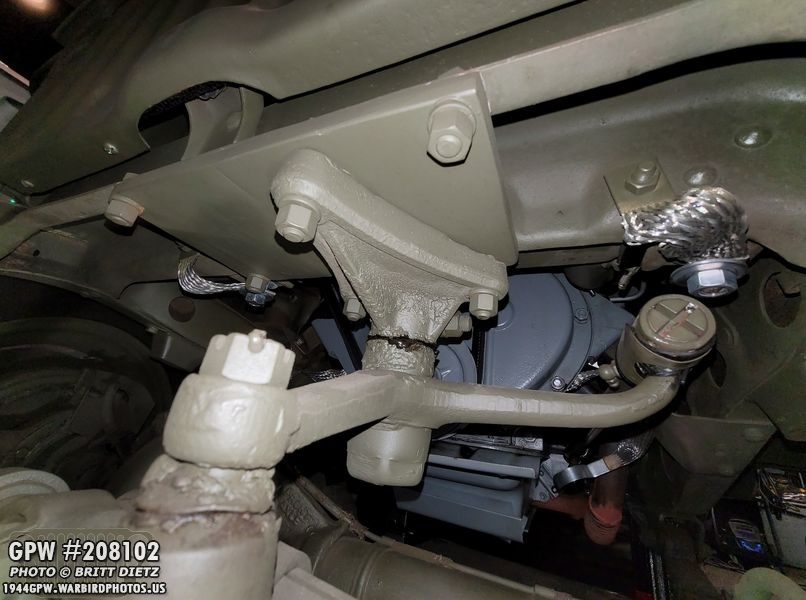
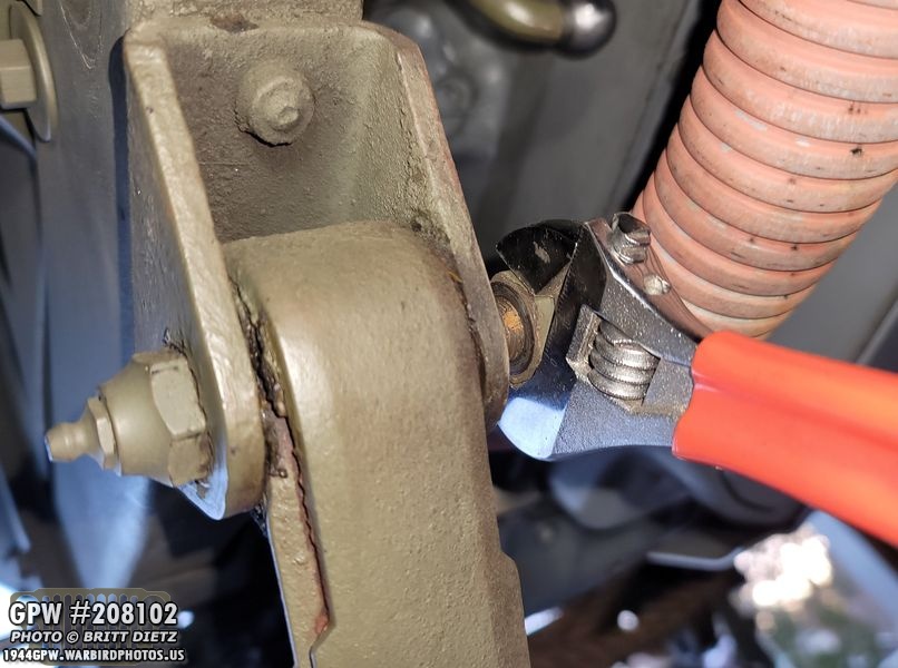
I wanted to point out the copper crush washer on the rear axle tri connector for the brake lines. In a previous update, I didn’t show that little detail, but it’s important to have that crush washer there to complete the seal.

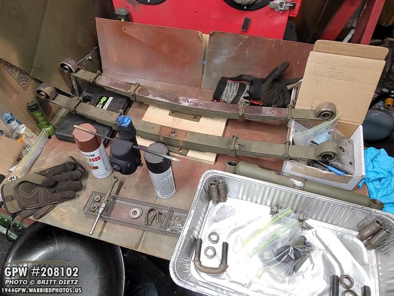
Last week, I put the springs back on one at a time after rolling the restored 1943 GPW rear axle.
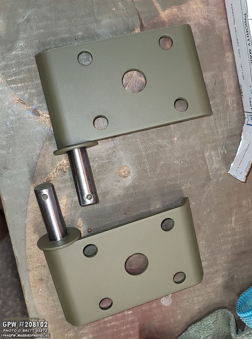
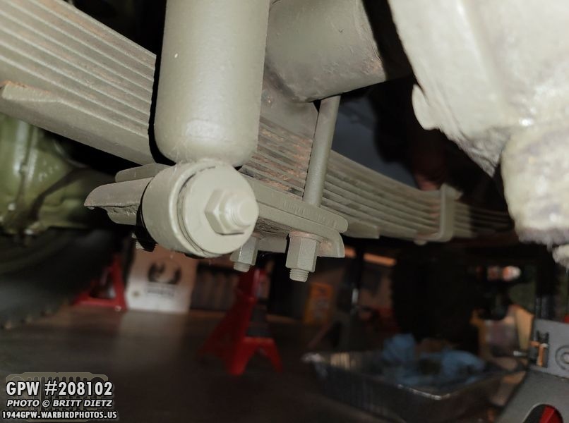
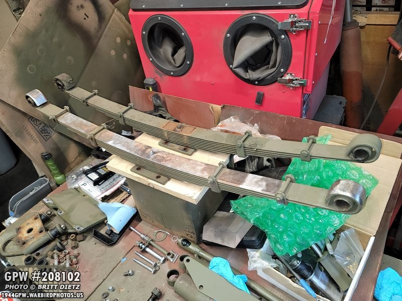
With the springs back installed, it was time to put on the leaf spring plates. These plates are important keeping the springs and the axle together with the U bolts (which go through the smaller holes). It also holds the bottom of the shocks. The ones that were on the CJ axles on my Jeep were CJ5 plates, so I had to get repro ones from &Ron Fitzpatrick Jeep Parts. This is the repros after painting.

The U-bolts were painted and ready to go. I didn’t paint the nuts OD Green as I knew they’d get scratched up as I tightened them.

With both springs installed, I went to work.

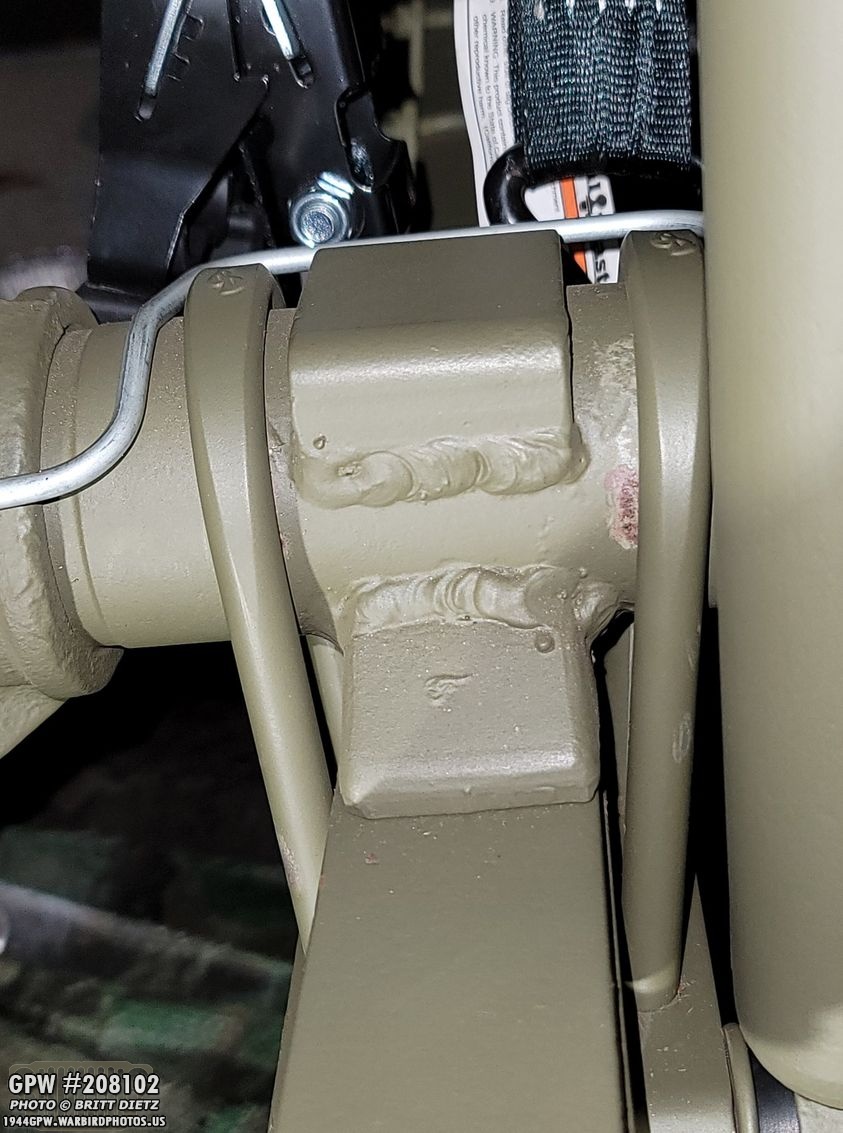
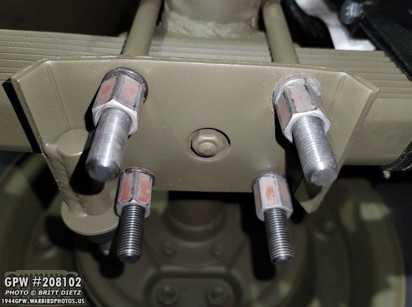
First, positioning the U bolts on the axle. I got them as close as I could to the top bracket on the axle shaft. The welding work on that bracket spilled over a bit, so I couldn’t make them snug. But, the wear pattern in the shaft tells me this is where the U bolts originally were on this axle anyway.

Getting the plate on can be a bit tricky, as the U bolts don’t want to slide in easy and will wobble around. Try to keep them as vertical as possible as you install this plate.

With the U bolts through, I began to put the nuts on with the lock washers. At this time, the first issue I’d have wasn’t apparent because the spring wasn’t pulled against the axle. Can you see what the first problem will end up being from this photo?
To make things even, before tightening the nuts, I went to the other side (passenger) and put the plate on, and started to tighten the nuts on there as well. But I instantly noticed an issue… the U bolts would NOT stay vertical, as you can see here. They kept wanting to pigeon tow outward. Have you figured out the problem yet?

How about now? It was at this point I started to realize the issue. I’ll give you a hint, it’s with the U bolts.

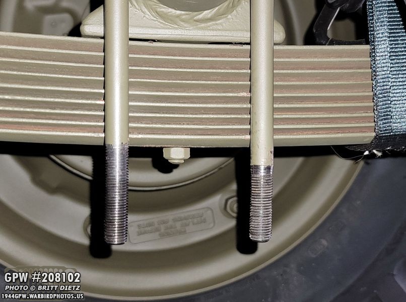
Here’s a good look at what the problem is. Imagine that plate under the spring here…. there’s not enough thread on the U-bolts! Doh!

Looking at the original U bolt I had gotten from Roger Smith (the blueish-green color), you can see there’s about 3/4 of an inch more thread on the U-bolt! The repro U-bolt is also longer. This probably wouldn’t be an issue if I had the later war 11 leaf rear springs, but mine are the earlier 9.

So, I got my 7/16 tap, and I went to make more thread, but I realized, I can’t do that. Not with this tool. Doh!

So I went and had to order a 7/16-20 hex tap, that will fit in a 1 inch socket. I also had to go get a deep 1 inch socket, as mine I have are not deep enough.

I ended up adding quite a bit of thread to the bolt. Here’s an example, with the left side having the extended thread. I actually went back and extended that a bit further.

I lined up the top of the original U bolt with the repro U bolt and used that as a guide to how high I needed to cut thread, then cut it a little further. You can also really see how much longer the repro U bolts are from the originals.
Just to be sure, however, I took the U bolt over to the rear axle and slipped it on. Notice how the thread now goes all the way to the spring? Much better!

Here’s a good chart to show the before and after with the U bolts. On top is the original, the two lower ones are repro. With all of them aligned at the top, the yellow arrow is where the original thread stops. The red arrow is where I tapped the thread extending it to. The blue arrow is where the repro U bolt thread originally stopped.
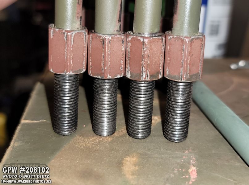
It took a long while, using oil to help lubricate the tap as it cut the threads, but I got all 8 (2 U bolts, 2 sides each) threads extended.
After that, the U bolts needing some paint touch ups, so I hit them with some 33070 OD Green again after sanding any scuffs.

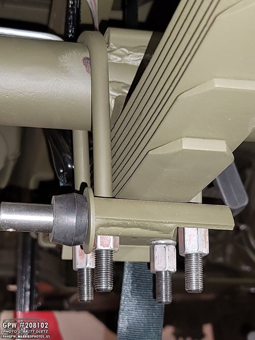
Time to install again! This should work perfectly, as you can see the thread levels will be beyond the plate.
I was excited, as it seemed to be working! But then, it came time to tighten the nuts. I had read on G503 to torque them to 45-foot pounds. What I didn’t know at the time, is that the TM manual actually states 50-55 foot pounds of torque on these nuts.

And here’s where the second major issue happened… As I was torquing them to around 30 foot pounds, I noticed that the nuts were not getting tighter. They just kept turning. I looked at the plate and saw this. UH OH. The steel has BENT from just 30-35 foot pounds and I’m running out of thread. It should not be doing this.
Looking underneath, you can see it’s bowing on both sides upwards as I tighten them. Ugh! At the time, I figured I’d just gotten a bad plate. The passender side had some slight warping, but I was able to torque it to 45 foot pounds at least.

I ended up contacting Ron Fitzpatrick Jeep Parts, who immediately shipped out a replacement plate. In the meantime, I left the bent plate on there, and touched up the paint on the axle.

Looking at the passenger side, you can see that it was slightly warped, but it was torqued to 45 foot pounds successfully.
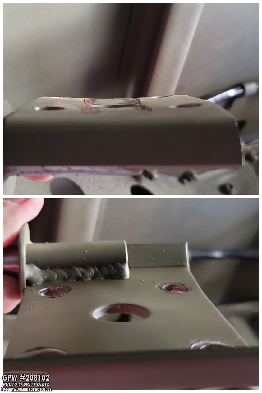
When I finally did take off the bent plate on the driver’s side, you can really see how much it warped. Why is this bad? Well, if it warps that easy at just 30-35 foot pounds, as the axle wants to push away from the spring, it’ll pull on the U bolts, which in turn pull on the plate. With that much bending, it could bend the plate even more making the U bolts come loose. That could be very bad.
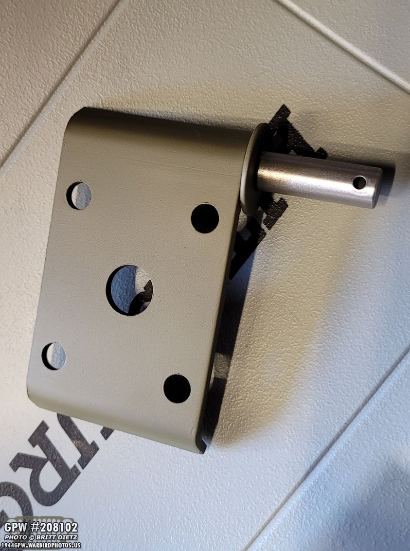
About two days later, the replacement plate came from Ron. I sanded it and painted it with the 33070 OD Green.
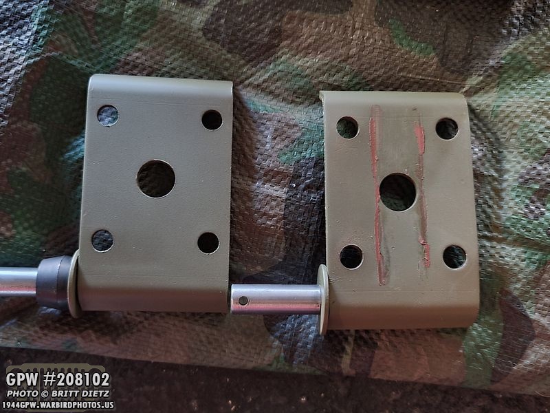
Here’s a comparison of the bent plate (right) and the replacement plate (left). The holes were slightly different in alignment weirdly.

So, I happily put the new plate on and began to tighten the nuts again… at about 35 foot pounds, I felt the familiar feeling of the plate bending. Ugh. After contacting Ron, it turns out that they are made with mild steel, so no matter what, I could never get them to 45 foot pounds, much less the 50-55 foot pounds that the 1942 and 1944 TM manuals state to do!

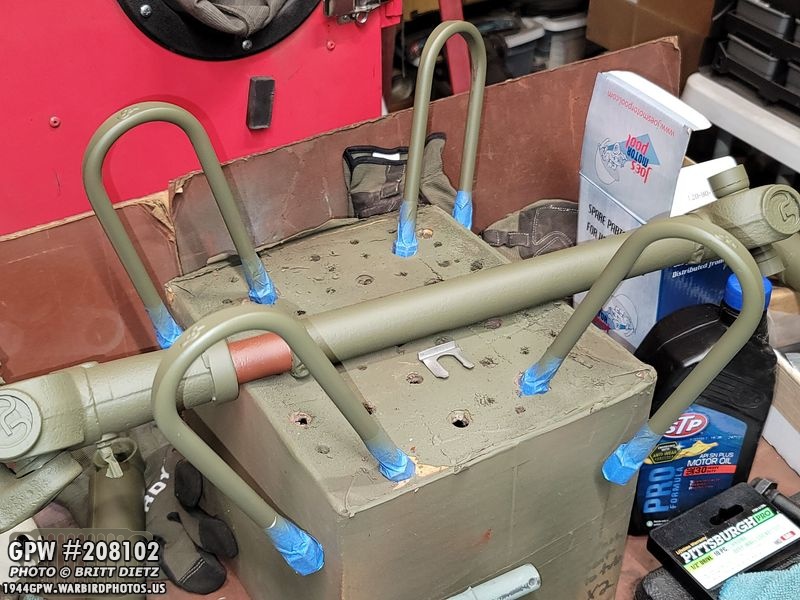
Feeling a bit defeated, I moved on to putting on the shocks to make sure there are no issues with that. I learned a nice trick from Scott Schiller from the G503 videos of using a ratcheting tie-down to compress the spring to the frame (as shown here). This allows you to put the shocks on, otherwise, the spring is too far apart from the frame to add them back on.
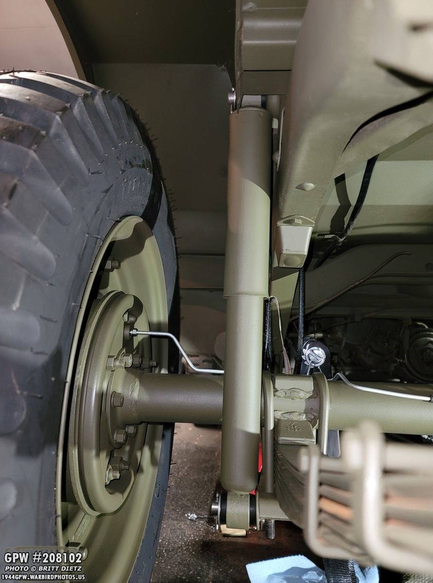
Thankfully, the original Gabriel shocks went on no problem. The new rubber bushings compressed and I was able to get the gotten pins in.

Knowing I’d have to take them off, I didn’t bend the cotter pins. But it’s nice to know these are ready to go when it’s time.
As I explored my options with those plates, and feeling like I’ve had delay after delay with the rear axle, I decided to shift gears to the front axle as I had a lot to do on that!

Unlike the rear shocks, the front shocks still have the shock bracket on the frame. It also appears that the shock has NEVER been removed from the bracket.
The bottom of the shock has the CJ5 style plate. I would have to replace that, but thankfully the Torque Reaction Spring (which was removed from my Jeep since the CJ axle and CJ steering was added) has that built-in, and I got a complete take-off TRS assembly.
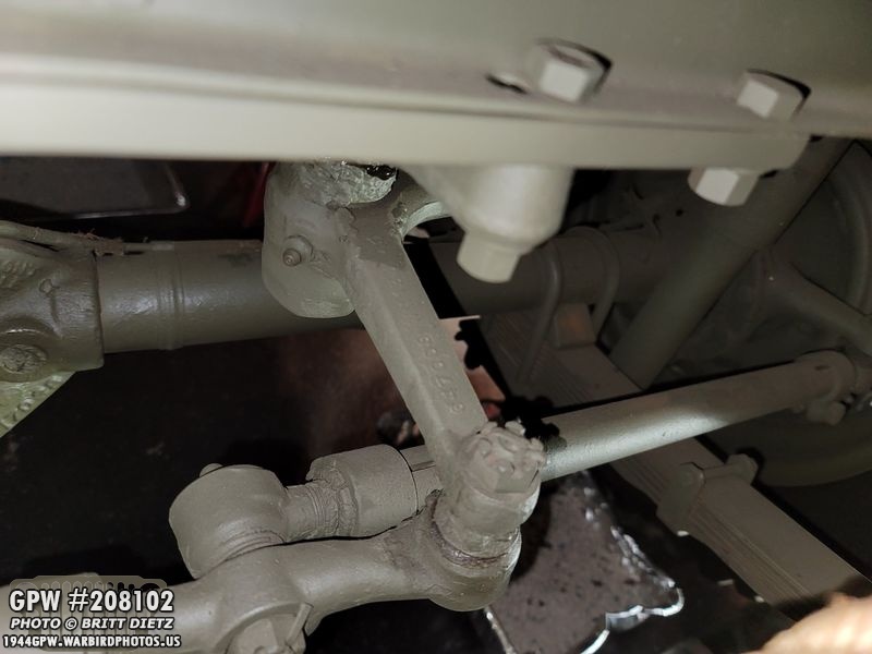
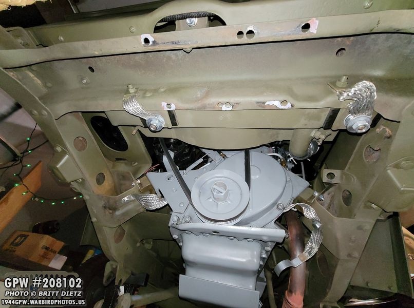
And here’s a look at that CJ steering system. Instead of the steering being attached to the front axle itself, the bell crank is instead moved to the cross member. So someone drilled holes to my crossmember, added a plate, then connected the CJ steering. This was done for post-war CJ jeeps to counter the left ‘pull’ that would occur when you would stop.
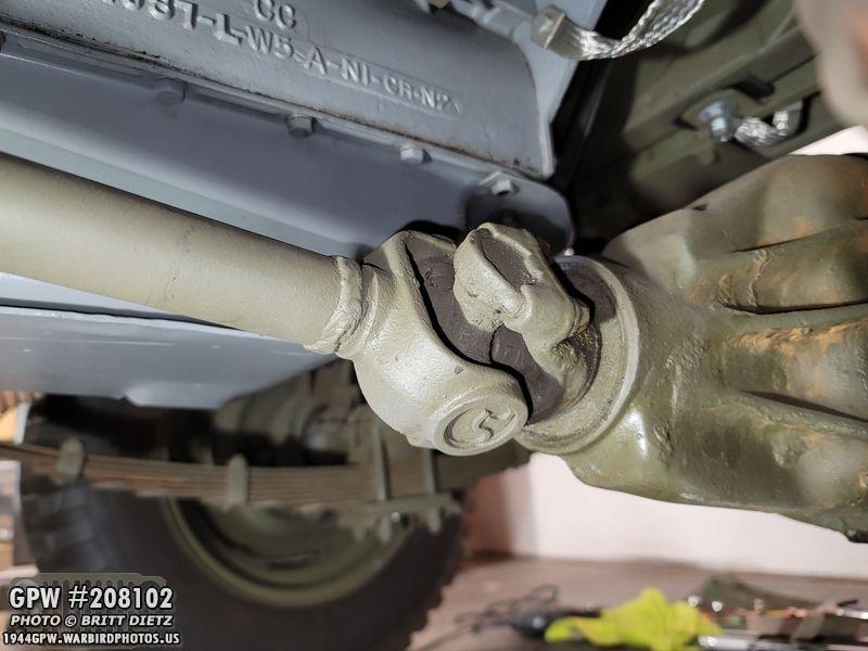
To start removing things, I first needed to remove the propeller shaft from the axle. I realized I’d need to remove the shock plate from the bottom of the Jeep to disconnect it from the transmission, so for now just separating it from this location will suffice.
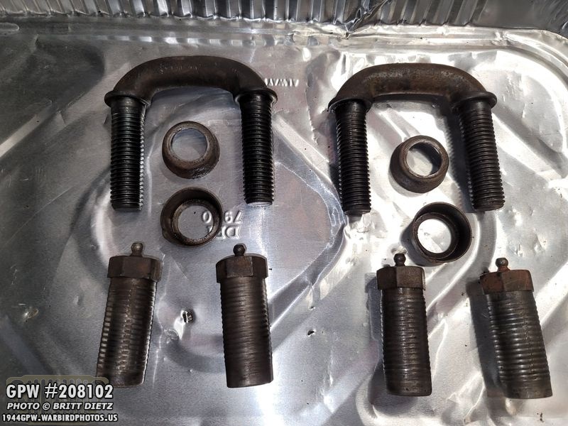
It’s been a while since the small U bolts have been removed from the shaft, but I got them to finally come loose. It helps to have the Jeep in 1st gear with 4 wheel drive engaged so the shaft doesn’t spin as you’re trying to break the U bolt nuts free.
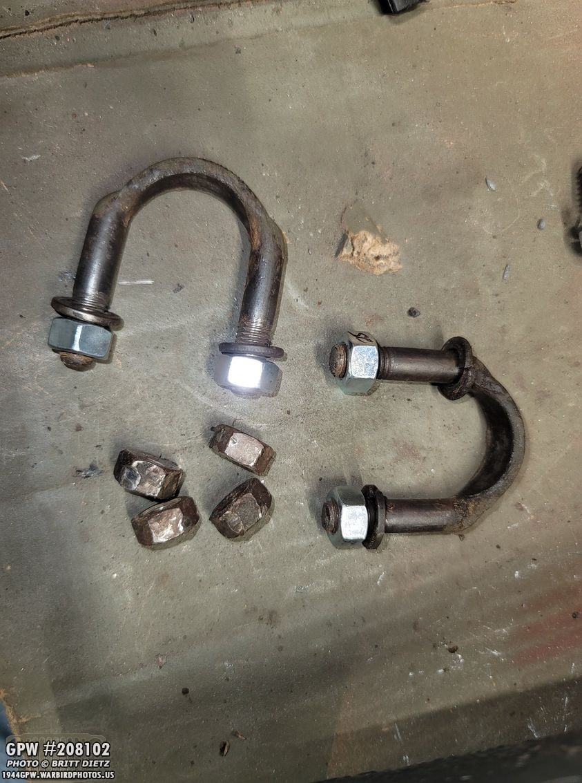
Here’s a look at the small u bolts for the shaft after I put them in gasoline to clean them off. The nuts looked pretty worn down, so I decided to use new nuts instead. This is an important part, so I’d rather have new safe nuts rather than ones that look to have 76 years of wear. The wrench was slipping on several of them as I was trying to free them due to the nut edges being worn down.

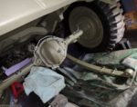
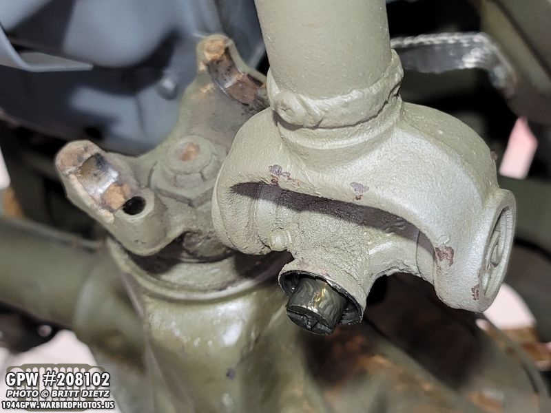
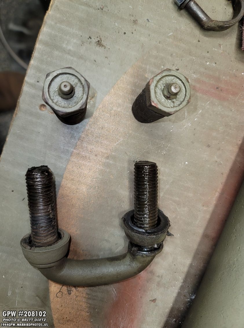
And I wanted to point out the caps on the propeller shaft. Inside the caps are tons of tiny needle rollers. This is a bearing of sorts. Normally, you want to be careful when you free the shaft that these don’t fall off and the needles spill out everywhere. I was lucky in that 1) the caps were on pretty good, so they wouldn’t come loose without some manual effort, and 2) the grease in the caps is strong enough to keep the needles from falling out.

The cotter pins on the top of the shocks were VERY hard to remove. But, after being in there for what is probably 76 years, it’s no wonder. The bottom of the shocks, with the CJ plates, just have a nut that needs to be broken loose. When the correct shock mounts are installed, the bottom will have the same washer and cotter pin installation as the top.

Here’s a look at both sides of the front with the shocks removed. I’ll wire wheel the shock mount pins so they don’t have any rust/paint.

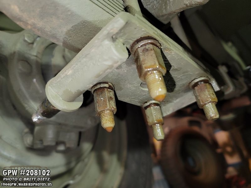
In prep for removing the CJ plates from the front (notice, no bend!), I heavily doused the nuts with PB blast.

It wasn’t easy. As with the rear plates, they fought me the ENTIRE way off. My electric rachet, which is 35 foot pounds torque, couldn’t get them off at ALL the entire way. I had to use my large rachet to slowly turn the nuts one thread at a time till they were off. This is the most tiring part.
Moving on to the other side, same thing as before… they were soaked in PB Blast.

Here’s a look at all the parts. Again, this is for a CJ axle. So the U bolts are larger (wider), there’s a spacer plate, and a CJ style leaf plate with the threads on the end instead of a cotter pin hole.

With the plates and shocks removed, it’s time to take off the springs!
I took one more shot of the CJ steering system. You can see how it connects to the bottom of the crossmember with the bell crank on that rather than the axle. From there it connects to the drag link (right) and the axle tie rods (left).
Moving back to the springs, I took the first shackle off. Pretty good shape, like the rears. Much like the U bolt nuts, the shackle cap nuts took a long time to get off, fighting me with each turn until they were off.
With both shackles off and the springs down on one side, I was able to roll out the axle once I disconnected the steering system from that crossmember and also disconnect the drag link for the steering. I then lifted the front of the Jeep with my shop crane up high enough that I was able to just roll out the axle. It was a bit of an awkward process as the crane got in the way of the axle, but it eventually worked. Sadly, it all went so fast and was so much work that I didn’t take any photos of that process. Doh!
Looking at the crossmember, you can see the holes that are left on it from the CJ steering that was added. It looks like whoever put it there might have mis0judged the holes so there are two extras. Ugh. I’ll have to fill all of them.

Here’s a look at the front axle now that it’s removed. This axle and the complete rear one are for sale if someone needs a CJ axle set! Everything included.

I took the drag link off next. To show how different the CJ drag link I removed is from an original GPW drag link I got to replace it, on the left is the GPW, on the right is the CJ. The CJ drag link is longer due to the steering on the crossmember being further out than the GPW/MB axle.

I wanted to add, since it’s been a while, a photo of my special tool I use to remove the cap nuts from the drag links. It’s a special socket that I got off Amazon, and I used a flap wheel to grind down the edges a bit more so it perfectly fits in the grooves of the nuts.
Final thing left to do is remove the springs, which means taking out the pivot pins. The driver’s side one is much harder to get to, as the engine and exhaust tube is in the way. I had to use a wrench to break the castle nut free and get it off. I was able to use a long punch with a hammer to get the pin out.
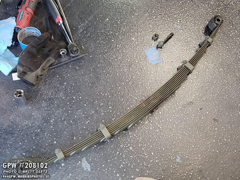
First spring removed!

Yuck. I’ll have to soak this in my bucket of gasoline to break up that crud.
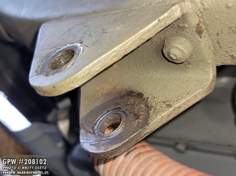
The spring brackets on the front seem to be in good shape with a little bit of wear from the springs. They just need to be cleaned up.

The next day, I started the process of wire wheeling the spring and the shocks to see what I have and do some investigating.
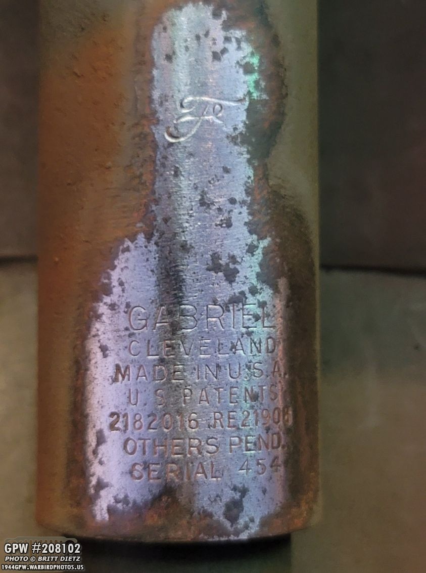
I found a lovely surprise on the first shock… unlike the rear shocks which have the same Gabriel information, this shock was positioned in a way that the F stamp wasn’t worn off! So cool! And both shocks still work GREAT.
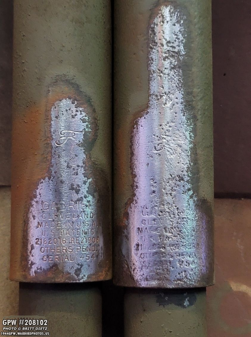
Sadly, while the other front shock has the same Gabriel info, as you can see, the way it was positioned it’s mostly pitted away that information. You can JUST barely see the bottom of the F stamp, but it’s also pitted away. Darn, but at least I have one with all the info clear as possible!

I decided to try and experiment with the shackles. I often dunk things in my ‘Bucket O’ Fuel’ (a 5-gallon bucket full of gasoline) to clean parts, but I also have a 1-gallon pail of ‘parts cleaner’. I wanted to see which cleans parts better from the initial cleaning to the sandblasting. So I decided to split it up, one shackle and all parts will go in the fuel, one will go in the parts cleaner. I’d leave them in for 2-days to soak.
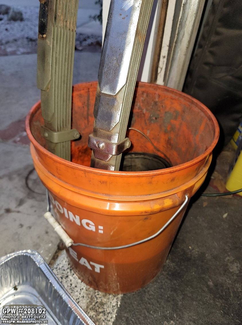
So, I put one shackle set in the bucket (shown here with the springs soaking in the fuel as well to remove that grime)

And I put the other shackle set in this pail.
Two days later, I pulled them out. On the left is the parts cleaner, on the right is the fuel. This photo was taken after I had taken a wire brush to both of them to quickly remove the residual paint. So, which was better?FUEL ————-The paint came off with almost no effort. I could literally wipe away it with a cloth. The grease was nearly gone or broken up. It also dries quickly with no worry it’ll rust the metal. CLEANER ——-The paint was lifting away, but there were some spots I had to really use the wire brush to break it off. The grease was still pretty thick in the caps, and unlike the fuel I had to clean the residual cleaner off in case it rusts it. I also had to wash it off. The winner? I still think the fuel is the BEST way to clean parts.

To help break up the rest of the grease in the shackle cap nuts, I soaked the inside with a degreaser for 24 hours.
And that’s where we are with the front. Shocks removed, springs removed, axle removed, and drag link removed. Now comes the tedious part of cleaning everything down to the metal and repainting.

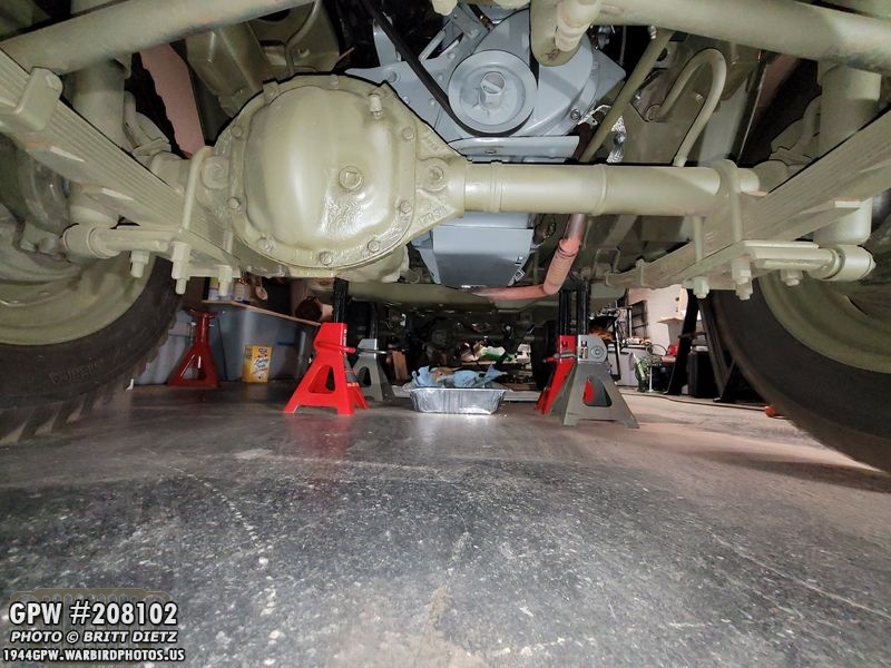
I will say, the Jeep looks quite funny without anything underneath the front.
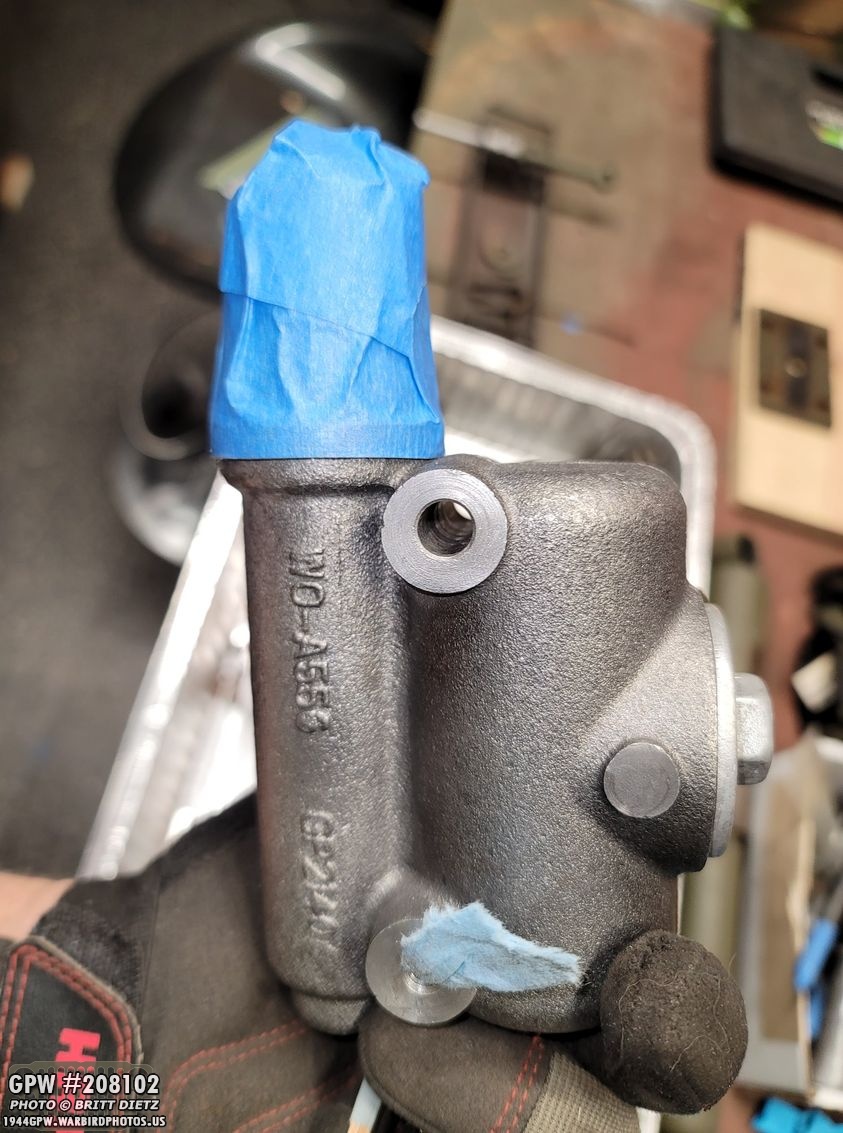
One final project I needed to get to was painting the new master cylinder for the brakes. Here I’ve masked off the rubber boot on the end and put some shop towel pieces in the screw holes.

I used a wooden dowel to hold onto the cylinder and primed it.

I then used a flat black (high heat) on top of that.

And once that was dry, I used a satin clear coat on top to give it a shine and protect the paint. Easier to clean as well!
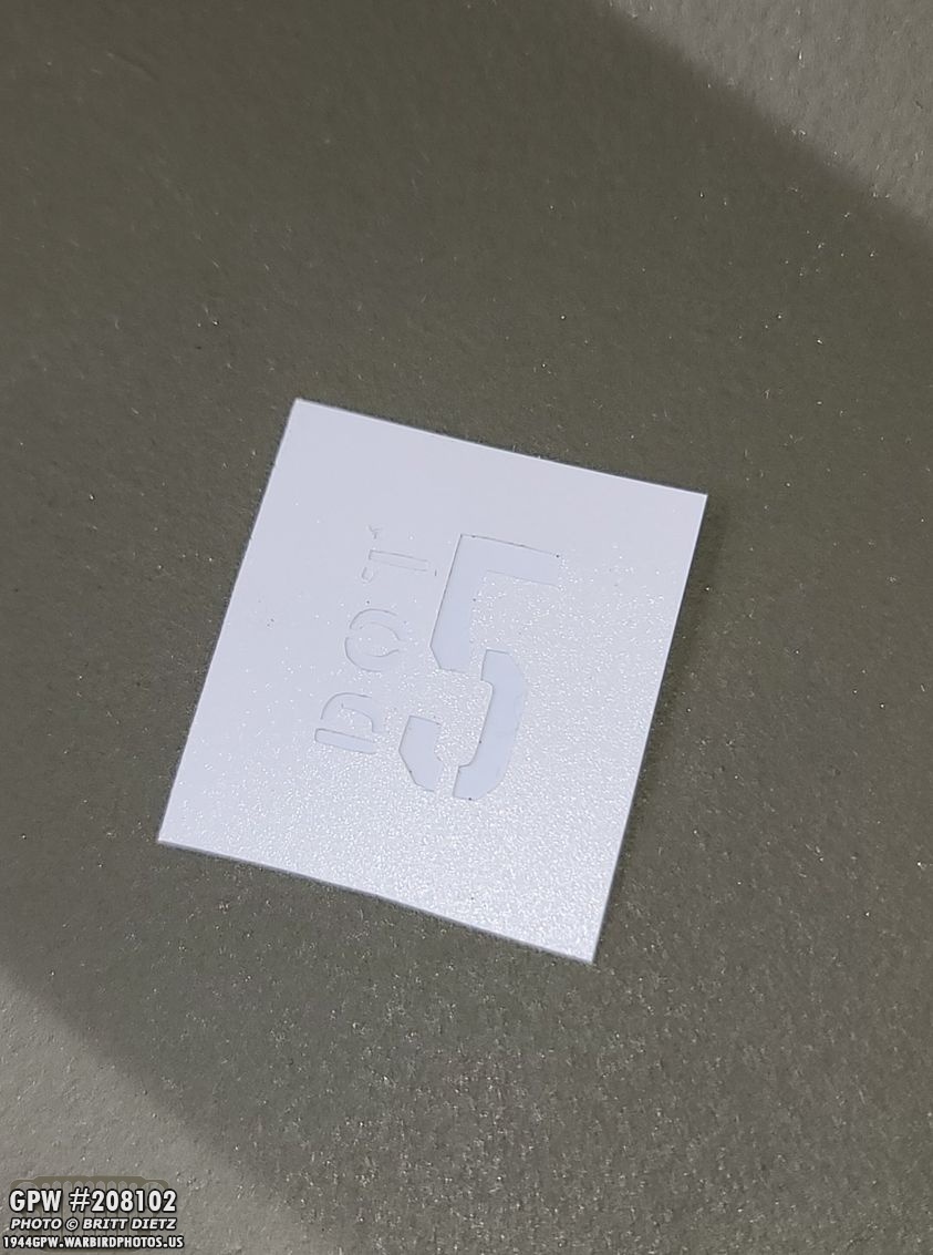
Finally, since I’m using DOT 5 brake fluid since I’m starting with a fresh brand new brake system, I wanted to make sure it’s known that the master cylinder has DOT 5. I used my Cricut with some WW2 stencil fonts to make this stencil.

Putting it on the cap, I originally was going to spray paint it, but I got lazy and decided to manually paint it with acrylic paint.

After I peeled off the stencil, I immediately regretted manually painting it, it’s not perfect. Oh well, it’s not like it’s seen and it does its job. I guess, shalk it up to some soldier putting this on! Ha ha. This will be the messiest stencil job on my Jeep.
So, that’s it for this week. Look for the long process of cleaning the springs, shocks, etc and repainting next week! Hopefully, by the first week or two of 2021, I’ll be able to drive the Jeep again! Till next week’s update…